


Making Sense of Drive-by-Wire
投稿人:DigiKey 欧洲编辑
2012-11-01
When you get into an automobile, you know what to expect. There will be a steering wheel with which you change the vehicle’s direction, a gear stick to set the gear, and two or three pedals on the floor that you press to accelerate and brake the car, and, in models with manual transmissions, to disengage the clutch so you can change gear. A parking brake, usually on the floor between the front seats, helps secure the vehicle at rest. It did not have to be this way: some of the earliest automobiles had accelerator pedals that you moved sideways, which made a lot of sense on the bumpy roads of the time. So why are most automobiles built to a pattern that has lasted for a hundred years or more?
One obvious explanation is interoperability. As a standard pattern for automobile control layouts emerged, customers already familiar with that pattern insisted on it in their next vehicles. The second reason is more subtle. Many elements of the standard control layout emerged because they represented the simplest way to make the mechanical linkages necessary to turn a driver’s inputs into physical force acting on the key mechanisms. Think of a rack and pinion steering system, with which a driver cranked the front wheels of an automobile into the right position, or the physical throttle linkages that connected an accelerator pedal to the butterfly valve on the carburetor.
As automobiles have become more complex and demands for comfort and safety have increased, the driver’s role in directly controlling the underlying workings of a vehicle have become increasingly mediated by other mechanisms. Human muscle power has been amplified by hydraulic systems to ease steering and braking; engines have become closely managed for greater efficiency and lower emissions by complex electronic systems; and even the driver’s driving intent, expressed as the angle of the steering wheel and the set of the accelerator, have been mediated by vehicle stability control and similar systems that stop the driver pushing the vehicle beyond its dynamic limits. You may think you are in the driver’s seat, but, in fact, you are in a partnership with complex systems that express a set of decisions made by automobile engineers in R&D labs miles away and years ago.
Drive by wire
Some of these systems, such as power-assisted steering and braking, which directly amplify the human input, have been widely accepted and used for years. A new class of driver aids, known collectively as ‘drive-by-wire’, takes the decoupling of human input and control output a step further by replacing direct mechanical linkages with arrangements of sensors and actuators.
These ‘steer-by-wire’, ‘brake-by-wire’ and ‘throttle-by-wire’ systems are seen by manufacturers as a way to cut the weight of vehicles by getting rid of complex mechanical linkage systems, as well as an important way to more closely integrate their drivers’ intent into the increasingly complex electronic control systems of the vehicle. Drivers may be less sanguine: although they will happily step on to a ‘fly-by-wire’ aircraft in which the pilot’s inputs at the flight yoke are just variables in a complex control system, there is something about being able to stomp on the brakes in a vehicle emergency that still has a visceral appeal. The fact that the braking systems are likely to be much more effective than they were twenty years ago thanks to the uptake of ABS, a mechanical way of simulating the cadence braking we were taught in driving school, often escapes them.
Drive-by-wire systems make extensive use of sensors to gather the driver’s input, check that it has been accurately reflected in the motion of the actuator it is controlling, and for health monitoring in complex ‘x-by-wire’ subsystems. The safety-critical nature of these systems also means that many of these sensors are doubled up, providing some redundancy as well as giving a system controller the inputs necessary for it to ‘vote’ on the correct action to take, as happens in some high-reliability and military systems. Sensors used in such applications need to integrate well with their control systems, as well as being able to withstand the harsh operating environments found in most automotive applications.
Throttle-by-wire
Throttle-by-wire systems rely on a sensor that measures the displacement of the accelerator pedal, and a second sensor that feeds back the throttle position. Some pedal sensors also sense the ‘wide-open throttle’ position as an input to automatic transmission systems, as a signal that the driver is trying to change gear by ‘kicking down’ on the accelerator.
Pedal position
Pedal position sensors can measure either rotary or linear displacement, depending on how they are linked to the pedal, with the sensor outputting an accurate voltage signal proportionate to the displacement. Some specialist pedal position sensors have dual outputs, to provide redundant signals, or offer two separate outputs that have different ranges for greater accuracy.
For example, the 140-0-0-103 from Vishay Spectrol is a wire-wound, 10 KΩ potentiometer with a linear output and a 330° operating range. Two important things about this pot in this context: it has a tolerance of ±5%, and a temperature coefficient of ±20 ppm/°C, giving it reasonable stability over the wide range of operating temperatures found in automotive applications.
The other way of measuring rotary displacement would be to use a Hall-effect sensor, in which the presence of a magnetic field influences the flow of current in a semiconductor device. The AS5048A and B from ams is a 360° angle position sensor with a 14-bit digital output, enabling it to offer a maximum accuracy of 0.05°, given that some linearization and averaging is handled by an external microcontroller.
The IC measures the absolute angle of the magnet’s rotation using an internal Hall sensor, analog-digital converter, and digital signal processing circuits. The zero position can be programmed over an SPI or I²C bus, which might be a useful alternative on production lines to trying to align a magnet physically.
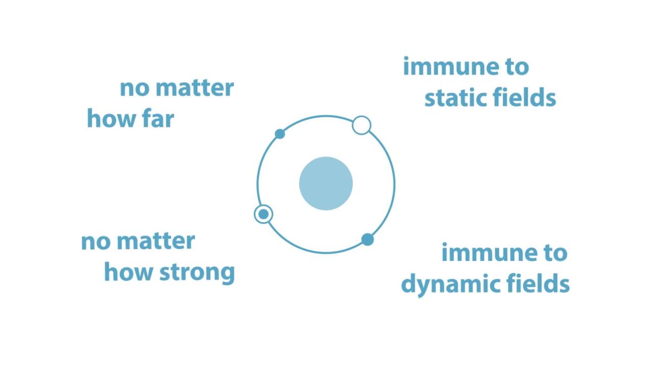
The company also claims the sensor will tolerate misalignment, variations in the air gap between it and the magnet it is sensing, and external magnetic fields. The operating temperature range is −40°C up to +150°C, which makes it suitable for automotive applications. The parts can also be daisy-chained, to simplify wiring, offer a PWM output that can be read out over a standard SPI or high-speed I²C interface.
If you want to integrate a pot that measures linear displacement into some sort of housing, then Spectra Symbol has the SP Series SoftPot, which is a linear position sensor, sealed to IP65, which can be ordered in a variety of lengths and resistance ranges to suit your application.

Figure 1: The structure of the SoftPot offering allows for customization.
The membrane potentiometer is made up of a conductive resistor, a sealed encasement and a wiper assembly, with a three-wire output so it can also function as a voltage divider. Spectra Symbol will also make custom versions of the SoftPot, including different-shaped tracks and even the option to have multiple tracks run next to each other, which would be useful if you wanted to use different resistance ranges to improve accuracy, or a second independent measuring track for improved redundancy.
Throttle position
Throttle position sensors are usually mounted on the spindle of the butterfly valve that lets fuel and air in to the engine. Their rotary position can be sensed as before: more sophisticated throttle-by-wire systems may include extra sensors to indicate when the throttle is fully closed. Non-contact Hall-effect sensors can be used to provide the ‘fully closed’ signal.
Brake-by-wire
Particular attention needs to be paid to the safety-critical aspects of brake-by-wire systems, leading to the use of more sensors to ensure redundancy and accuracy.
A brake-by-wire system will include pedal sensors, much like those used in the throttle-by-wire example, as well as sensors in the electric calipers that are used to apply the brake pads to the brake disc. These sensors measure how fast and how firmly the brakes are being applied. The speed of rotation of each wheel also needs to be captured so the braking control system can apply the brakes in a way that does not cause skidding.
Incremental encoders can be used to sense relative position, although designers have to take care to compensate for any error they might accumulate over time. Parts such as the 63R Encoder Series from Grayhill offer up to 256 cycles per revolution, are rated to last for up to 300 million revolutions, and for shaft rotation speeds of up to 5000 RPM.

Figure 2: The two outputs of this incremental encoder are out of phase, allowing the detection of absolute angular position – as well as the rejection of common-mode noise.
Two outputs are provided, with one leading the other by 90° ±45°, allowing the detection of absolute angular position. These outputs also help suppress common-mode noise, which is always useful in electrically noisy environments such as vehicle control systems. Designers need to develop signal-conditioning and processing circuits to extract accurate position and speed estimates from the sinusoidal signal outputs.
Clamp force sensors can be expensive, as they have to be engineered into mass-produced subsystems, yet work to very tight tolerances and at extremely high temperatures. The sensors are very likely to need calibrating on the automotive production line, further increasing the cost of using them. Some designers are looking at ways of eliminating the need for clamp-force sensors by using combinations of other sensor inputs as a proxy for direct measurement of the clamp force.
Steer-by-wire
Hydraulically assisted steering has been with us for years. Now, some automobile makers want to get rid of the weight and complexity of the hydraulic subsystems and steering column that enable powered steering and replace them with electric steering controlled from an electrically sensed steering-wheel position.
Other advantages include the increased flexibility in interior design that doing away with the steering column gives vehicle designers, the ability to program different steering characteristics for different situations, and the reduction of vibration and noise from hydraulic systems. Vehicle assembly may also be simplified by designing the steering as a standalone module that just needs wiring up, rather than a lot of mechanical integration.
Again, this is an area that demands extreme attention to safety, as well as design strategies that emphasize redundant control signals and fail-safe behavior.
Sensor solutions for steer-by-wire systems tend to be produced as complete subsystems by specialist suppliers, but their sensing elements rely on the same principles used elsewhere in the automobile to meet the x-by-wire sensing challenge.
免责声明:各个作者和/或论坛参与者在本网站发表的观点、看法和意见不代表 DigiKey 的观点、看法和意见,也不代表 DigiKey 官方政策。


 中国
中国