Log Amps Meet RF Power-Measurement, Signal-Scaling Needs
投稿人:电子产品
2015-08-27
The logarithmic amplifier (usually referred to as a log amp, sometimes as a log detector) is an analog component used in RF circuits and electro-optical interfaces. Its transfer function is conceptually simple: the output voltage or current is proportional to the logarithm of the input voltage or current (Figure 1). It implements this input/output relationship over an input range of 60 to 80 db (typically), but it can be as large or as wide as 120 dB in some cases; some log amps even reach 160 dB of dynamic range. While it is called an “amplifier” it is not one in the customary sense of the word; it is really a linear-to-logarithmic converter.
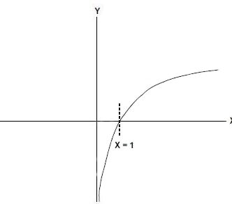
Figure 1: The logarithmic amplifier, or converter, produces an output current, or voltage signal (Y axis), which is proportional to the logarithm of the input current, or voltage signal (X axis); note that it is undefined for inputs equal to or below zero, although log amps have ways around this limit.
It may seem counterproductive to deliberately place a nonlinear component in a system, given all the emphasis on component and circuit linearity and resultant low distortion over a wide range. The log amp is part of the design, but it is usually not directly in the signal chain. In RF circuits, it is often part of the closed-loop control which adjusts the receive-channel gain via automatic gain control (AGC) to maintain a near-constant signal level in the channel by measuring input signal strength over a wide range (RSSI—received signal strength indicator), Figure 2, as well as to control transmitted power. In optical circuits, it is used to monitor the current to the laser diode and adjust for changes due to temperature and other operational factors.
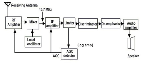
Figure 2: As this FM-receiver block diagram shows, the log amp is often used in the AGC feedback loop of a receiver to maintain signal levels in a narrow range despite a wide range of input signal strengths.
Although the logarithm function is undefined for arguments equal to or less than zero, real-world circuits do have non-positive signals. Therefore, log amp designers use a variety of techniques to work around this limitation. Log amps and their applications fall into three broad groups:
- The DC log amp (“DC” is somewhat of a misnomer) is used for slowly changing signals, up to about 1 MHz. It is used for the optical-circuit power control, as well as for medical, chemical, and biological instrumentation.
- The baseband log amp is used in audio and video circuits when some sort of signal compression is needed, as well as IF stages of receiver signal chains and the signal-processing path of ultrasound circuits. It has a symmetrical output for positive or negative input signals, with an output which is positive for positive inputs and negative for negative ones.
- The demodulating log amp both compresses and demodulates RF signals, and its output is the logarithm of the rectified signal’s envelope. This log amp is used in RF-transceiver applications, where received RF-signal strength is used to control transmitter output power. The output is based on the absolute value of the input, and is positive regardless of whether the input is positive or negative.
[Note that the log amp is not the same as another nonlinear analog amplifier, the limiting amplifier. That device, sometimes called a clipping amplifier, is linear throughout most of its range. However, when the input approaches positive or negative maximum, the amplifier gain begins to decrease and limit. Thus, rather than just hard-saturate the output — which causes severe distortion and also may take a relatively long time for the amplifier to recover — this amplifier “soft limits” and reaches maximum output relatively gracefully; when the input returns to the normal range, the output quickly returns to linear mode as well.]
Log-amp design
The log amp’s core is based on the well-known logarithmic relationship between the current through, and voltage across, the PN junction of a diode, (Figure 3 left), and used in conjunction with an op amp in a practical circuit, (Figure 3 right). Starting with this basic physics principle, log amps use many topologies and configurations, each providing trade-offs among various performance attributes and priorities as the accuracy and bandwidth require. While the internal details may not be of direct interest to the log-amp user, they do affect the fit between log amp and application. Log amps which provide a highly accurate transfer function – a characteristic needed in some applications, but not in others – are often called “linear in dB” log amps.
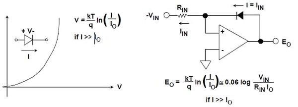
Figure 3: The well-known current vs. voltage relationship of a diode is the basis of nearly all log amp designs (left); to make use of this diode relationship, it is placed in the feedback loop of a basic op-amp design (right).
For RF applications, the successive-compression log amp uses multistage amplification and progressive limiting to develop a close approximation to the logarithm in a piece-wise manner. They include a rectifier (detector) with each of five to ten low-gain stages (8 dB to 12 dB each), whose outputs are summed to produce a filtered voltage that is a decibel-scaled measure of average power, over a 100 dB and greater range.
Other RF applications use an exponential-gain design which has reduced gain span (around 60 dB) but greater accuracy; it usually includes a single detector whose filtered output makes the detector into a square-law device, with the output being the power-equivalent (rms) value of the applied signal.
Log amps for optical applications usually are in the “DC class” since they measure relatively slow-changing currents related to optical power, to control the current in the laser diode or the gain of optical-mode amplifiers. They may need do this over a range from about several picoamps up to several milliamps, a total of nine decades (109:1 span).
Log-amp specifications
The physical implementation of a log amp can be as an integrated circuit (IC) or as a module comprised of individual die and discrete components, The IC versions are smaller, cheaper, and use less power, among other virtues, and can provide very good performance; they are usually the first choice to consider. The hybrid construction is used when the singular process technology of an IC, and thus a single IC, cannot adequately meet all the required parameters of the application such as noise, bandwidth, or temperature range.
Log amps have some specifications which are similar to conventional, non-log amps, as well as some which are unique due to the nature of the device. Also, different vendors may have legitimately different definitions for some of these parameters, so it is critical to check the data sheet for the details and test conditions. Top-level factors include:
– Dynamic range in decades: usually specified in dB, and will range in most cases from 60 dB to 120 dB (or more). Wide range may not be needed in all situations, and achieving it may come at a trade-off of degrading other key specifications.
– Bandwidth: for today’s RF applications, this will usually be in the single-digit GHz range, but some advanced devices can reach tens of GHz.
– Accuracy: the conformance to a perfect linear/logarithmic transfer function. It is typically between 0.1% and 1%, but also may vary depending where in the input range it is measured.
– Sensitivity: the lowest signal value which the log amp can process; usually, it is in the 1 nA or 1 μV range, but can be lower; it is often specified in dBm, usually at 50 Ω.
– Offset: the output of the log amp when the input is at its minimum (not 0, since log 0 is undefined).
– Fixed or adjustable reference: some log amps have a fixed scale factor, such as 0.25 V/decade (or 10 mA/decade); others allow the user to supply a reference which determines the scale factor. Scale factor can be called out with respect to dB or decade, such as 20 mV/dB or 400 mV/decade.
– Unipolar versus bipolar inputs and outputs: the log of a negative number is undefined, yet many real-world signals are bipolar with negative values; to overcome this constraint, baseband and demodulating log amps use offsets, squaring, or other techniques to allow inputs below 0 V.
Among the two most challenging issues for log amps are noise and temperature coefficient (tempco). Since log amps work over many decades, they are expected to handle signals in the μV, nV, or even pV range (or μA, nA, or pA). However, if the signal levels are that low, the internal noise of the log amp may overwhelm the signal. For many RF applications, fortunately, low noise is not as critical as range and bandwidth, as long as the noise spectral density is low enough (usually on the order of nV/√Hz)
Tempco is the most challenging parameter for log-amp designers and users. Since the core of a log amp is based on semiconductor junction behavior, it will unavoidably change with temperature. Log-amp designers use a variety of design techniques to cancel, compensate, trim, or minimize tempco, but it is still a factor which is part of the trade-off in overall performance. As with many analog components, log amps are available with detailed specifications called out for standard commercial, extended industrial, and even military temperature ranges.
Log amp examples show span of specifications
Log amps are available from many analog and mixed-signal IC vendors. Manufacturers usually provide an error-compliance overview curve, along with detailed curves showing the conformance at specific frequencies and at low, nominal, and high temperatures at each of those frequencies.
For example, the AD8318 from Analog Devices is a demodulating logarithmic amplifier which uses the progressive compression technique over a cascaded amplifier chain, each stage of which is equipped with a detector cell (Figure 4). It provides accurate log conformance for signals of 1 MHz to 6 GHz and provides useful operation to 8 GHz. The input range is typically 60 dB (with a 50 Ω input impedance) with error of less than ±1 dB (Figure 5), and while stability over temperature is ±0.5 dB. The 4 mm × 4 mm, 16-lead device is specified over a –40⁰C to +85⁰C range and operates from a single 5 V supply.
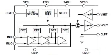
Figure 4: The AD8318 log amp from Analog Devices uses a cascaded amplifier chain and a progressive compression technique, yielding accurate log conformance for signals of 1 MHz to 6 GHz, and useful operation to 8 GHz.
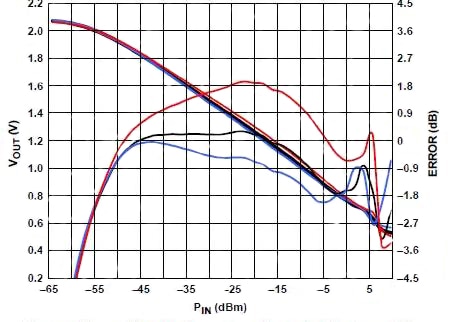
Figure 5: One of many detailed performance graphs which vendors provide for log amps, this graph of AD8318 output voltage VOUT (nearly straight descending line) and log conformance(“wiggly” line) vs. input amplitude at 8 GHz also shows performance at +25°C (black), −40°C (blue), and +85°C (red).
Linear Technology Corp. offers the LT5537, a wide-dynamic-range RF/IF detector which operates from 10 MHz to 1 GHz, (Figure 6). At 200 MHz, its dynamic range is 90 dB with ±3 dB nonlinearity (50 Ω input) as shown in Figure 7. The detector output-voltage slope is 20 mV/dB (nominal), and the temperature coefficient is 0.01 dB/°C at 200 MHz (typical). Sensitivity, also measured at 200 MHz, is at least –76 dBm. It operates with a single supply between 2.7 V and 5.25 V and is housed in an 8-lead, 3 mm × 2 mm package.
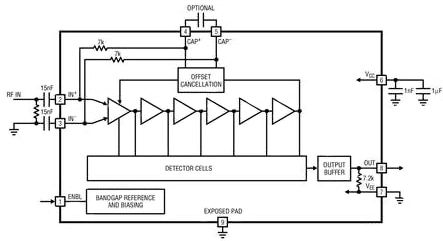
Figure 6: The LT5537 provides a log-linear relationship between the input and its output; the input signal is amplified by a series of limiting amplifier stages; a series of detector cells rectify the signals and produce an output current which is log linearly related to the input power.
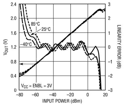
Figure 7: This is a broad overview of output voltage and linearity error vs. input power at 200 MHz, and at three temperatures, the Linear Technology LT5537 is supplemented by a large number of more-detailed performance graphs.
A third example is the MAX4003 from Maxim Integrated. Their MAX4003 low-power logarithmic amplifier is designed to detect the power levels of RF-power amplifiers (PAs) operating from 100 MHz to 2500 MHz, (Figure 8). With typical dynamic range of 45 dB, this log amp matches wireless applications including cellular handset PA control, transmitter signal-strength control for wireless terminal devices, and other transmitter power measurements.

Figure 8: Maxim's MAX4003 log amp is a low-power component for 100 MHz to 2500 MHz, with range of 45 dB; comprises four 10 dB amplifier/limiter stages, each with a small-signal gain of 10 dB; the output of each amplifier/limiter stage is applied to a full-wave rectifier and detector stage also precedes the first stage for a total of five detectors.
This voltage-measuring device accommodates a typical signal range of -58 dBV to -13 dBV, and is housed in a variety of tiny packages, including an 8-bump chip-scale, µMAX, and thin QFN packages. The vendor offers a high-level overview conformance diagram for different frequencies (Figure 9), as well as more detailed conformance diagrams for each of the frequencies cited, including temperature and even package type. The device requires 5.9 mA with a 3.0 V supply and only 13 µA when the device is in shutdown. It offers temperature stability achieved over the full operating range of -40°C to +85°C.

Figure 9: Packaging affects performance as well, as shown in the Maxim MAX4003 data sheet for VOUT and log conformance vs. input power at 2.5 GHz for the 8-lead μMAX package (left) and their 8-bump chip-scale UCSP™ package (right).
Summary
Although they have far more intricate and subtle specifications than conventional linear amplifiers, logarithmic amplifiers play key roles in both RF and optical systems. Log amps with GHz-range response are used to manage the front-end gain of a receiver as well as the transmitted power, while lower-frequency log amps are used to measure the current through a laser diode in a fiber-optic link.
There are many ways to build a log amp, with most based on a core of the unique logarithmic voltage/current transfer function of a diode. A practical, complete log amp is far more complicated than the diode alone, however, and must accommodate and trade-off dynamic range, bandwidth, temperature drift, noise, and the specifications of other performance parameters. Today’s log amps in IC form provide excellent performance in small, relatively low-power and low-cost packages; the hybrid, multi-chip log amp implementations are increasingly needed only in fairly specialized situations.
For more information about the parts discussed in this article, use the links provided to access product pages on the DigiKey website.
免责声明:各个作者和/或论坛参与者在本网站发表的观点、看法和意见不代表 DigiKey 的观点、看法和意见,也不代表 DigiKey 官方政策。


 中国
中国