ISM-Band Remote Keyless Entry Systems Add Value to Diverse Applications
投稿人:电子产品
2011-06-08
Keyless entry using a short-range, relatively secure wireless connection has many opportunities beyond opening automobile doors. Connected to a solenoid, remote keyless entry (RKE) systems can unlatch storage units, pet doors or secure entry gates. An even wider range of applications involve executing the common process of turning things on or off, such as lights, alarms and appliances.
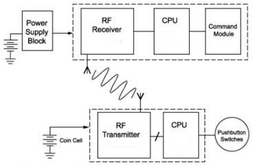
The basic RKE system operates in the 433-MHz ISM band and uses a 3-V lithium battery such as a CR2032 that lasts for several years. Current consumption is typically less than 8 mA. Components include four inexpensive ICs: a transmitter, a receiver and two identical microcontrollers that encode and decode a 24-bit key code. The basic RKE system, as shown in Figure 1, can be implemented with fewer than 20 components.
 Amplitude-shift keying (ASK) modulation is used in remote keyless entry systems to maximize battery life. (Courtesy: Maxim Integrated Products) |
A pushbutton switch – typically on a key fob – initializes the system by waking up the CPU housed inside the key fob, which sends a data stream to a radio frequency (RF) transmitter. Data is typically 64 to 128 bits long and consists of a preamble, a command code and a rolling code. To extend battery life, amplitude-shift keying (ASK) is used as the modulation scheme. The RF receiver captures the RF signal, demodulates it and sends the data stream to the CPU, which decodes it and the command module. This could be something as simple as a solenoid.
The transmitter design implemented in this article consists primarily of a Maxim MAX1472 transmitter, an Atmel ATtiny9 microcontroller, a 13.56 MHz crystal (the Crystek 016877, for example), an assortment of capacitors and inductors, and an antenna.
The MAX1472 is a PLL-based ASK-transmitter that operates in the 300 to 450-MHz band and integrates a crystal reference oscillator. It was designed for low-cost applications and runs directly off a lithium cell. The MAX1472 can operate as low as 2.1 V and consumes only 100 nA of current in stand-by mode. During transmission, it can output from -10 to +10 dBm of power into a 50-W load. When a dipole antenna is used, the transmitter has a range of at least 15 yards. The frequency selected for this design is 433.920 MHz because the PLL multiplies the 13.56-MHz crystal frequency by 32.
The ATtiny9 microcontroller generates a code key and transmits it by modulating the transmitter IC. The ATtiny9 integrates 1Kbyte of flash memory and an internal RC clock. When the key fob’s control button is pushed, the MCU reads a calibration byte (that must be set once during the design phase) from the flash memory and writes it to the oscillator calibration register. This procedure is used to optimize the accuracy of the MCU’s clock.
RKE Receiver
The receiver design is based on a Maxim MAX1473 receiver chip. This 300 MHz–450 MHz super-heterodyne ASK receiver features high sensitivity of -114 dBm, user-selectable center-frequency image rejection of better than 50 dB and the option of running from either 3- or 5-V supplies. A PLL oscillator provides the reference frequency.
The MAX1473 integrates an audio filter to reduce noise and interference. A data slicer placed behind the filter provides an automatic operating point adjustment when the signal is weak. The MAX1473 also integrates an image rejection mixer that eliminates the need for a pre-selection filter at the input and therefore reduces the component count.
An ATtiny9 MCU is used to decode the signals provided by the data slicer output of the MAX1473. When the decoded data contains the correct key, the MCU in the receiver circuit can activate two types of outputs. The first can be used to drive a mechanical latch opener operated by a solenoid. The second output can be used to switch devices such as control units, alarm systems, or an automobile’s anti-start device off or on.
Configuration
The hardware design of an RKE system is fairly straightforward. Much of the functionality and added value lies in the software. The receiver and transmitter require different programs, and other design tasks include the generation of a key code and close attention to timing issues.
A random number generator can be used by the transmitter to generate a key code and while there are several ways to do this, one technique that is widely used pairs the precise timing of the crystal with the imprecise charging time of an RC circuit. When combined, the two can generate random numbers.
Users must be sure to keep the receiver synchronized with the transmitter. Irregularities such as noise pulses on the supply line can result in a hung system, and the receiver must be capable of recovering from this and other types of irregularities. To help allow recovery, a data slicer is integrated into the MAX1473 in the receiver. A data slicer is a comparator with a reference level that is automatically reset when a data signal with a 50 percent duty cycle is received. From a software perspective, Manchester coding is typically used to attain this result.
免责声明:各个作者和/或论坛参与者在本网站发表的观点、看法和意见不代表 DigiKey 的观点、看法和意见,也不代表 DigiKey 官方政策。


