Integrating Energy Harvesting and Future Wireless Modules
投稿人:DigiKey 欧洲编辑
2016-08-30
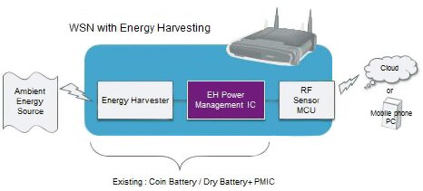
Using wireless modules opens up new ways to implement cost-effective sensor nodes for applications such as the Internet of Things (IoT). The simplicity of the modules, and the use of low power wireless protocols, allows energy harvesting sub-systems to capture energy from the environment to store locally, as shown in Figure 1. This can reduce or even eliminate the need to replace batteries and allows developers to implement sensors in many more inaccessible places.

Figure 1: A wireless module can be powered by energy from the environment to reduce the need to replace rechargeable batteries in a sensor network. (Source: Spansion)
Figure 2 shows the different wireless technologies and their suitability for using energy harvesting as a source of power. Protocols such as EnOcean have been specifically developed for energy harvesting applications with simple low-power techniques and structures such as telegrams, while others, such as Z-Wave, ZigBee and Wireless HART, are low-power extensions of existing wireless or industrial protocols that can also be used.
| EnOcean | Z-Wave | ZigBee | Wireless Hart | Bluetooth LE | Bluetooth | Wi-Fi | |
| Industry Organizations | EnOcean Alliance | Z-Wave Alliance | ZigBee Alliance | HART | Bluetooth SIG | Bluetooth SIG | Wi-Fi Alliance |
| Frequency Band | 315 MHz, 868 MHz, 900 MHz, 920 MHz | 900 MHz | 868 MHz, 915 MHz, 2.4 GHz | 2.4 GHz | 2.4 GHz | 2.4 GHz | 2.4 GHz, 5.8 GHz |
| Data Rate | Low | Low | Low | Low | Medium | High | Very High |
| Range (Depends on RF power) | ~50 m, ~300 m | ~30 m | ~100 m | ~250 m | ~50 m | ~100 m | ~100 m |
| Power Consumption | Very Low | Medium | Very Low | Very Low | Very Low | Low | High |
| Application | HEMS, BEMS | Sensor NW, HEMS | Sensor NW, HEMS, BEMS, Factory Automation | Factory Automation | NotePC, Smart Phone, Wearable, Medical, Sensor NW, HEMS, BEMS | NotePC, Smart Phone, PC peripheral | PC, Smart Phone, Digital AV, Indoor/Outdoor NW |
| Suitable for Energy Harvesting? | Very Good | Good | Very Good | Very Good | Very Good | Not Bad | Bad |
| HEMS: Home Energy Management System | BEMS Building Energy Management System |
Figure 2: Different wireless protocols have a range of power requirements making some more suited to energy harvesting sources. (Source: Spansion)
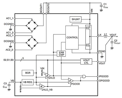
The MB39C811 from Cypress Semiconductor is a high efficiency buck DC-DC converter, which uses an all-wave bridge rectifier and comparator. This supports energy harvesting from an energy source of the high output impedance such as the piezoelectric transducer.
It is possible to select from eight preset output voltages and supply up to 100 mA of the output current with a quiescent current (No load, Output in regulation) of just 1.5 μA and an input voltage range of 2.6 V to 23 V. The preset output voltages range from 1.5 V and 1.8 V, through 2.5 V to 3.3 V and 3.6 V for low-power wireless modules. The outputs of 4.1 V, 4.5 V and 5.0 V are less likely to be used for such modules.
The device also features protection functions such as a shunt for input protection when Vin exceeds 21 V, as well as an over-current limit and I/O power-good detection signal output.
Figure 3 shows the structure of the power management device, which would be delivering the captured current to an energy storage device such as a capacitor or a rechargeable battery and then used to power a wireless module.

Figure 3: The MB39C811 from Cypress Semiconductor handles the power from an energy harvesting source to store in a rechargeable battery for a wireless module.
Interfacing the device to the wireless module requires consideration of a number of different factors. The energy supplied by the harvesting process will not be enough for the initial startup phase of a wireless transmission, and so it will be important to ensure that the drain from the storage device will not be excessive. This can be achieved by paying close attention to the processing requirements of the module. For example, at a clock speed of 12 MHz in the wireless module, a routine takes 1.1 ms to complete but consumes only 4 mA peak current. This is considerably less than operating at say 48 MHz; and while it uses more current, the peak current is lower and more appropriate for the energy harvesting architecture.
The bootup of the wireless module is a key challenge for the energy harvesting source. This includes initializing memory, setting interrupt vectors, configuring peripheral and common registers and initializing any external clocks. Each of these steps takes CPU processing time to complete, which in turn consumes energy.
The amount of power required for each of these stages can be minimized by initializing only those sections of memory and registers that will be used and leaving others to the default settings.
Initializing the clock oscillators can also take significant amounts of power. Instead of waiting in active mode for the clocks to stabilize, keeping the system in sleep or deep sleep mode allows the module to settle down. An internal timer can be used to then wake the module up for use. This avoids putting more strain on the energy harvesting power manager.
Using a wireless module often eliminates the need for a separate microcontroller or memory, making the development of a wireless sensor node simpler. However, the energy budget for the module needs to take into account how peripherals on the module will be used. These peripherals could be internal to the device, such as an analog-to-digital converter that connects to a sensor, or a direct connection to an external sensor. While the starting time may not be large individually for peripherals, the combined overall setup time could require enough processing time to drain the stored energy.
This requires the startup time of individual peripherals to be determined for a given CPU frequency. The different peripherals will also demand time from the central processor, and the power drain of this has to be taken into account to make sure that the total current drawn does not exceed the current available in the energy storage.
This can be achieved by profiling the code with software tools often supplied by the module or chipmaker.
If the current consumption does exceed the capacity of the energy storage, routines can be broken down into smaller subroutines to be managed in stages. This reduces the load on the storage element to smaller current pulses that can be more easily recharged by the energy harvesting source.
It is also advisable to place the system into a low-power mode between each of these stages, using a watchdog or timer as an interrupt. The module will be in low-power modes for the majority of the time, and this will keep the current requirement as low as possible, allowing the storage element to be more easily recharged.
Figure 4 shows the pinout for using the device with a solar cell as an input. This can be connected to a module such as the programmable versions of the XBee and XBee-PRO from Digi that use the ZigBee protocol. Programming directly on the module eliminates the need for a separate processor, and because the wireless software is isolated, applications can be developed with no risk to RF performance or security.

Figure 4: Using the MB39C811 with a solar cell input to power a wireless module using a protocol such as ZigBee.
The modules are based on the Ember EM35x (EM357 and EM3587) system-on-chip (SoC) radios from Silicon Labs that use the 32-bit ARM Cortex-M3 processor. The S2D EM3587 version has a larger memory footprint for developers who may want to upgrade to Thread, an IPv6-based networking stack, but this will increase the power consumption.
The module is connected up via the VCC, GND, Dout and Din pins, although the digital general purpose I/O pins can be used to connect to external sensors. To support serial firmware updates, the RTS and DTR pins are also connected.
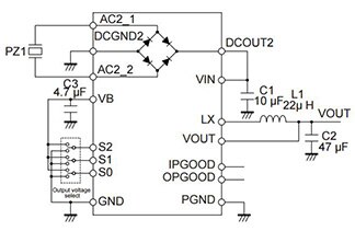
Figure 5 shows the pinout for using the MB39C811 with an oscillating energy source such as a piezo electric crystal. In this scenario, the vibration of equipment causes compression of the crystal, stressing the crystal lattice and creating current. This can then be captured by the PMIC device.

Figure 5: Using the MB39C811 with a piezoelectric source to generate power for a Bluetooth wireless module.
Interfacing to a Bluetooth Low Energy module such as the CYBLE-022001-00 from Cypress Semiconductor allows a low-power wireless node to be implemented. The module supports a number of peripheral functions such as ADC, timers, counters and PWM, as well as serial communication protocols (I2C, UART, SPI) through its programmable architecture. The CYBLE-022001-00 includes a royalty-free BLE stack compatible with Bluetooth 4.1 and provides up to sixteen GPIOs in a small 10 × 10 × 1.80 mm package.
The CYBLE-022001-00 contains two power supply connections, VDD and VDDR. The VDD connection supplies power at 1.71 V to 5.5 V for both digital and analog operation, while the VDDR connection supplies power for the device radio with a range of 1.9 V to 5.5 V. The maximum power supply ripple for both power connections on the module is 100 mV, which can be handled by the MB39C8111 and the storage element.
Conclusion
Using a wireless module with an energy harvesting sub-system opens up many new possibilities for a wireless sensor network, but requires attention to the overall power budget. The lower current produced by the energy harvesting, whether a solar cell or piezoelectric source, means that the startup sequencing and the sensor management software have to be carefully considered. By scheduling these carefully, and if necessary breaking down routines into smaller units, the developer can make sure that the peak current requirement does not exceed the capacity of the battery and the capacity of the energy harvesting source to recharge it. All of this can be managed by the latest power management devices that are specifically optimized for this type of power sub-system.

免责声明:各个作者和/或论坛参与者在本网站发表的观点、看法和意见不代表 DigiKey 的观点、看法和意见,也不代表 DigiKey 官方政策。


 中国
中国