How to Ease the Installation Challenge of the Smart Home with Energy Harvesting
投稿人:DigiKey 欧洲编辑
2016-01-12
There are many different ways of using energy from the environment to power sensors in the smart home. Solar energy can be harvested both outdoors and, with today’s high efficiency cells, from indoor lighting. Thermal energy generators can provide power from a temperature difference for actuators on radiators and windows, and it is even possible to harvest small amounts of energy from the movement of switches. Harvesting power in this way allows sensor and actuator nodes to be placed in any location in the home without having to worry about access to main electricity or access to change the batteries. This creates a much stronger appeal to the homeowner who can easily add sensors that can connect to an existing wireless network.
One of the most developed approaches is to make use of the ambient lighting in the home, where a well-lit room has around 400 lux of illumination, falling to 100 to 200 lux in the shadows. This compares to 10,000 to 100,000 lux from outdoor illumination. The amount of power generated depends on the size of the array, so there is a balance between the size of the wireless node that can host the array and the power requirements that can be met by that array.

Figure 1: The Amorton solar cell array uses amorphous silicon and a glass or plastic substrate.
Panasonic’s Amorton technology (as shown in Figure 1) uses amorphous silicon so that the solar energy conversion cells can be connected together during manufacturing to create any desired output voltage. This allows the arrays to support a range of output voltages from 1.5 V to 3.0 V to power both the wireless transmitter and the sensor.
| Model | Typical operating characteristics (Initial) | External dimensions (mm) | Weight (g) | |
| FL-200lux | FL-50lux (Reference value) | |||
| AM-1456 | 1.5 V- 5.3 μA | 1.4 V- 1.30 μA | 25.0 X 10.0 | 0.7 |
| AM-1411 | 1.5 V- 8.0 μA | 1.4 V- 2.00 μA | 29.6 X 11.8 | 1.0 |
| AM-1437 | 1.5 V- 8.0 μA | 1.4 V- 2.00 μA | 29.6 X 11.8 | 1.0 |
| AM-1407 | 1.5 V- 11.5 μA | 1.4 V- 2.85 μA | 38.0 X 12.5 | 1.3 |
| AM-1417 | 1.5 V- 12.5 μA | 1.4 V- 3.10 μA | 35.0 X 13.9 | 1.3 |
| AM-1424 | 1.5 V- 20.0 μA | 1.4 V- 5.00 μA | 53.0 X 13.8 | 2.0 |
| AM-1454 | 1.5 V- 31.0 μA | 1.4 V- 7.75 μA | 41.6 X 26.3 | 3.0 |
| AM-1513 | 1.8 V- 15.0 μA | 1.6 V- 3.75 μA | 55.0 X 13.5 | 2.0 |
| AM-1805 | 3.0 V- 15.5 μA | 2.6 V- 3.85 μA | 55.0 X 20.0 | 3.0 |
| AM-1801 | 3.0 V- 18.5 μA | 2.6 V- 4.60 μA | 53.0 X 25.0 | 3.6 |
| AM-1815 | 3.0 V- 42.0 μA | 2.6 V- 10.50 μA | 58.1 X 48.6 | 7.8 |
| AM-1816 | 3.0 V- 84.0 μA | 2.6 V- 21.00 μA | 96.7 X 56.7 | 15.6 |
Figure 2: The different sizes of the Amorton solar cell array from Panasonic can be matched to the voltage and current requirements of a smart sensor or actuator.
As a result, an Amorton solar array measuring 55.0 × 20.0 mm generates a 3 V output from 200 lux with a current of 15.5 µA, as in the table in Figure 2. This is sufficient to power a bi-directional link from a low power transceiver such as EnOcean’s TCM300 linking to a device such as a proximity security sensor. Making the array smaller to 29.6 x 11.8 mm generates 8.0 μA at 1.5 V to power a one-way link for an application such as a carbon dioxide monitor, which only needs to send a simple data telegram if the sensor falls outside a pre-set range.
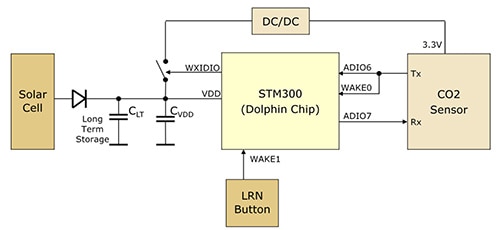
The transmitting current for the STM is 24 mA, so a capacitor is used to build up sufficient power for both the module and for any sensor. This is shown in Figure 3, where the transmitting module also acts as the interface to a carbon dioxide sensor.

Figure 3: Combining a solar array with an STM300 transceiver from EnOcean and a CO2 sensor for a wireless carbon dioxide monitor in the smart home.
New designs of CO2 monitors from companies such as Gas Sensing Solutions in Scotland use a mid-infrared light source and detector technology with new optics to reduce the power consumption to 3.5 mA in continuous operation so that it can be powered by energy harvesting sources. New sensor designs support measurement ranges of 0-2000 ppm, 0-5000 ppm and 0-1% with a fast warm-up in 1.2 seconds so that the monitor can be powered down until used, reducing the power requirement.
One of the challenges of a CO2 sensor is that it drifts with time. With a dual-channel approach, one channel measures the CO2 concentration while the other measures the sensor signal intensity. This calibration can be handled daily to ensure that the sensor is accurate, and this can be scheduled when enough power has built up from the capacitors and timed to avoid any transmissions which will also drain the power source.
Such sensors are automatically self-calibrating and can operate without batteries for up to 16 hours in total darkness. The sample rate is automatically varied (between 9 and 2 samples per hour) according to the light levels or can be fixed at 10, 15 or 30 minutes. Adding an optional rechargeable battery means the sensor can operate in very low light conditions for approximately 10 years.
It is even possible to harvest the energy generated by a rocker switch such as the PTM200 from EnOcean. In this case, the energy comes from a built-in electrodynamic energy transducer actuated by a 1.8 mm bow, which can be pushed from outside the module on the left or right by an appropriate pushbutton or switch rocker (Figure 4). This can be used for wall-mounted flat rocker switches as well as handheld remote controls with up to four buttons, all without needing a battery.

Figure 4: The PTM200 rocker switch generates enough power from the movement of the switch to send a wireless message.
When the bow is pushed down, the 7 N force generates enough current for an RF telegram to be transmitted with the 32-bit ID of the module. Releasing the bow generates different telegram data, so every PTM telegram contains the information that the bow was pressed or released, as well as the time taken so that ‘short’ and ‘long’ operations can be easily detected. This allows the rockers to be used for applications such as dimming control.
This also allows the switches to be easily installed without having to worry about AC-DC or DC-DC converters from the power lines for the lights themselves, and allows remote controls to be independent of any batteries, which is a tremendous advantage for any home system.
Energy harvesting allows the integration of other sensors, such as proximity detectors to detect motion, for security systems. The Si1145-M01 reflectance-based, ambient light module from Silicon Labs has an integrated single infrared LED, two additional LED driver outputs, an I2C digital interface, and programmable-event interrupt output to act as a proximity detector. The module integrates the LED and detector into a single chip to reduce any interference between the source of the light and the reception. This is helped by the photodiode response and associated digital conversion circuitry that provide immunity to artificial light flickering and natural light flutter that can be a problem with proximity sensors.

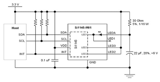
Figure 5: The Si1145 ambient light module has been optimized for low power operation as a proximity sensor that can be powered by a solar cell array and linked to a wireless transceiver as a host controller.
The device runs from a 1.71 to 3.6 V supply voltage, so there is no problem with using a solar cell array as the source. The average current of 9 µA is also well within the power delivered by the array and is a key consideration for the design. This average current is kept low by pulsing the LED for 25.6 µs every 800 ms at 180 mA, and with a standby current under 500 nA. The trigger to wake up can be internal or external, and the device includes a built-in voltage supply monitor and power-on reset controller to further support the use of a solar array and link to a wireless transceiver as a controller, as in Figure 5.
Supporting the varying input power from an energy harvesting source, the LED current of each output is independently programmable from a few milliamps to several hundred. This allows the designer to optimize the design for the proximity detection performance or for dynamic power saving with a smaller solar cell. Additionally, this allows the host to reduce the LED current once an object has entered a proximity sphere, and the object can still be tracked at a lower current setting.
All of these low-power modes are essential in supporting the operation of the proximity sensor and its integration with a wireless module, both powered by a solar array.
Conclusion
The efficiency of solar arrays and other energy harvesting technologies has evolved tremendously over the last few years to provide the 1.8 V to 3 V supplies that system designers need. As the power consumption of sensors and controllers has also dropped, and device manufacturers have paid more attention to the peak and average current consumption of the chips, so the ability to power smart devices in the home from the energy in the environment has become a practical proposition, with even the kinetic energy of a switch providing enough power.
By paying attention to the overall current requirement of a design, solar cell arrays can now be sized to provide the current and voltage that enables sensors to be coupled with wireless transceivers and placed throughout the home without worrying about replacing batteries or supplying power.

免责声明:各个作者和/或论坛参与者在本网站发表的观点、看法和意见不代表 DigiKey 的观点、看法和意见,也不代表 DigiKey 官方政策。


