


How Phase Shifting Can Help Improve the Performance of DC/DC Converters
投稿人:电子产品
2016-04-07
Modern electronic system boards are populated with ICs like FPGAs, DSPs, microprocessors, memories, and ASIC chips. In addition, there are audio amplifier and RF-power-amplifier modules on board associated with sound and wireless communications. Each device or module on such a board has a different requirement for voltages and current. Consequently, in a distributed power architecture, these semiconductor devices and modules are powered by a variety of switching point-of-load (POL) DC/DC converters that derive their inputs from a common bus voltage to generate the required voltage or voltages for these semiconductor ICs and modules.
Generating a number of regulated DC output voltages from a single source imposes high-root mean square (RMS) current ripple and noise problems on the DC input source. To address the noise issue, designers typically use input filtering at additional cost. Because each switching converter is using a different switching frequency, beat frequencies between 100 Hz and 23 kHz are generated, which can degrade the performance of system audio amplifiers.
Recently, Intersil published a white paper1 describing how the input RMS current ripple and noise can be minimized by preventing the on-time overlapping of these multiple, on-board DC/DC converters using phase-shifting techniques. In reality, this technique also improves EMI and eliminates the need for input filtering, while tackling the problems linked with beat frequencies.
This article examines how multiple DC/DC buck regulators are organized in a master/slave configuration using phase-shifting time delays to improve the noise performance on the source input of these on-board DC/DC converters. It also demonstrates the implementation of the phase-shifting time delay technique using Intersil’s synchronous buck regulator ISL8018, which is tailored for this design. In addition, by synchronizing multiple DC/DC converters using the same clock, the article also shows that beat-frequency problems can be eliminated from the system.
Master/slave configuration
Figure 1 shows DC/DC converters configured as in-phase and out-of-phase for a three-phase solution. The total output current is 24 A with each phase converter optimized to deliver 8 A. In the phase-shifted version using three converters, each converter is phase shifted 120°. If desired, more phases can be added for higher output current capability.

Figure 1: Three DC/DC converters configured with no phase shift and with phase shift.
As per the white paper, the RMS input current is governed by equation 1:
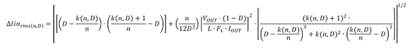 .. (1)
where n is the number of phases, D is the duty cycle, L is the output inductor, Fs is the switching frequency and k (n,D) is the mathematical floor function. In essence, k (n,D) = floor (n*D), which means it basically returns the lowest integer value of the function. For example, if there are three converters operating at 50 percent duty cycle, then n = 3 and D = 0.25. The floor (n*D) = floor (3*0.5) = floor (1.5) = 1. Likewise, if n = 3 and D = 0.25, floor (3*0.25) = floor (0.75) = 1.
Based on calculations using the equation for RMS input current, the Intersil designers generated a plot of ΔIIN_RMS (n, D) versus duty cycle, which is depicted in Figure 2. In reality, ΔIIN_RMS (n, D) is a ratio of the output current and RMS input current, explains Intersil’s applications manager Tu Bui. To ensure accuracy, Bui says, the calculated plot was verified with a measured response. Intersil’s synchronous buck regulator ISL8018 was used for this design as it provides the required SYNCIN and SYNCOUT features to implement the phase-shifting time delay. The plot indicates that phase shifting significantly reduces the RMS-input current ripple for n = 3.

Figure 2: A plot of RMS-input current ripple ΔIIN_RMS (n,D) versus duty cycle.
Key benefits of the out-of-phase approach are shown in Table 1. Besides lowering the RMS-input current ripple, phase shifting also reduces input voltage ripple. The input ripple frequency also increases, thereby simplifying filter design.
| Parameter | In-Phase | Out-of-Phase |
| Number of Phases, n | 3 | 3 |
| RMS Input Current | 10.8 A | 3.1 A |
| Input Voltage Ripple (10 mΩ RESR capacitor) |
240 mV | 80 mV |
| Input Ripple Frequency | 1 MHz | 3 MHz |
Table 1: Benefits of out-of-phase operation over in-phase design.
Using the buck regulator ISL8018’s SYNCIN and SYNCOUT features, a master/slave configuration for implementing phase-shifting time delay is shown in Figure 3. In this scheme, the SYNCOUT pin of the master switching regulator sources a current pulse, ISYNC, starting at every clock cycle. The current source terminates and discharges to 0 V after it reaches the 1 V SYNCOUT voltage. The detection threshold for the SYNCIN pin of the slave regulator is 0.9 V. When each rising edge of SYNCIN reaches 0.9 V, the on pulse of its phase is triggered. Simply adding a small, inexpensive capacitor across SYNCIN to ground changes the SYNCOUT current source slew rate.

Figure 3: Master-and-slave circuit diagram using synchronous buck regulator ISL8018.
As per the white paper, the phase-shift time delay t in ns is equal to 2.8*CPHASE in pF. However, the manufacturer’s data sheet cautions that care must be taken to include PCB parasitic capacitance of ~3 pF to 10 pF. As this capacitance is in the pF range, a low-cost NPO or C0G dielectric-class ceramic capacitor with a tight tolerance of ±1 percent can serve its needs. Accordingly, the phase-shift tolerance is about 5.12 percent, says Intersil. A practical implementation of the master/slave configuration with three phases using ISL8018 regulators is illustrated in Figure 4. As shown, it can be scaled with more or fewer regulators.

Figure 4: A practical implementation of the master/slave configuration with three phases using ISL8018 regulators.
Eliminating beat frequency
When multiple DC/DC converters operate from the same input bus at different switching frequencies and in close proximity to one another, it results in beat frequency that can be further amplified by the system’s audio amplifier, creating interference and audio noise in the system that can be problematic. The synchronization capability of the ISL8018 can eliminate this problem.

Figure 5: The difference between frequencies f2 and f1 of the two close converters results in the beat frequency Fb.
Figure 5 shows the beat frequency Fb which is the difference between frequencies f2 and f1 of the two converters with the same input source and in close proximity. The white paper indicates that the beat frequency Fb will show up in the ground-ripple voltage noise when there is no isolation (Figure 6). The SYNC feature of the ISL8018 solves this problem by allowing the switching frequencies of the ISL8018 regulators to be synchronized using a common master clock. It results in Fb equal to 0 Hz, thereby eliminating the beat frequency problem in a system.

Figure 6: Ground-ripple voltage noise due to beat frequency Fb.
In short, synchronous buck DC/DC converters like ISL8018 can easily implement phase-shifting time delay techniques to provide a low-cost solution to reducing RMS-input current ripple and noise, and eliminating beat frequency problems on boards where multiple converters are powered from the same input bus and operate at different frequencies. For slightly lower current (up to 6 A), the manufacturer recommends ISL8016 for this application.
For more information on the parts discussed in this article, use the links provided to access product pages on the DigiKey website.
Reference
- White paper “How to Improve DC/DC Converter Performance with Phase Shifting Time Delay” Intersil Corp., November 2015.
免责声明:各个作者和/或论坛参与者在本网站发表的观点、看法和意见不代表 DigiKey 的观点、看法和意见,也不代表 DigiKey 官方政策。


 中国
中国