Harvesting Energy for Data Transmission in Industrial Automation Applications
投稿人:DigiKey 欧洲编辑
2013-01-30
This article looks at the detailed requirements of energy harvesting for data transmission systems in industrial automation networks, interfacing solar and thermal energy systems to low power nodes, and the implications of the different protocols on an energy harvesting supply.
It covers the CAN and LIN protocols, with the Microchip MCP202 family of LIN transceivers and the NXP TJA1015 CAN devices, as well as the EnOcean EDK312C and Cymbet CBC-EVAL-09 thermal energy harvesting development kits. It also covers how the Texas Instruments bq25504 power management device provides the right power to the transceivers from the energy harvesting sources.
Falling voltages and power consumption for industrial networking transceivers is bringing energy harvesting to wired devices. Now, networks using the CAN and LIN industrial protocols can make use of energy harvesting technologies for transmitting data across the factory floor. This may be to reduce energy costs or provide network nodes without having to install new wiring for power, as these network protocols do not support self-powering in the same way as Power over Ethernet (POE).
Using energy harvesting with older generation devices has not been possible, and the 5 V and higher voltages, means the power consumption has been too high. As both CAN and LIN come from the automotive heritage, the original designs support voltages as high as 12 V, but the new process technologies are now driving the transceivers to 3.3 V and below. This heritage means that the protocols are robust and resistant to interference, and the devices are qualified for industrial temperatures.
However, this still means the energy harvesting system requires power management and some storage to take the input captured from thermal, vibrational or solar energy, and provide a high enough power output for the network node.
The different network protocols provide a range of advantages, from the low cost of LIN to the more flexible CAN.
LIN
The LIN Protocol was designed by a consortium of European automotive manufacturers as a low cost, short distance, low-speed network, and has moved into the industrial arena with some success. Designed to communicate changes in switch settings and respond to switch changes, it is intended to communicate events that happen in "human" time (hundreds of milliseconds).
Bus features
The LIN Protocol supports bi-directional communication on a single wire, while using inexpensive microcontrollers driven by RC oscillators, to avoid the cost of crystals or ceramic resonators. Instead of paying the price for accurate hardware, it pays the price in time and software. Transfer rates of up to 20 Kbaud are supported, along with a low power SLEEP mode where the bus is shut down to prevent draining the battery, but the bus can be powered up by any node on the bus.
The bus itself is a cross between I²C and RS232, where the bus is pulled high via a resistor and each node pulls it low, via an open collector driver like I²C. However, instead of having a clock line, each byte is marked via start and stop bits and the individual bits are asynchronously timed like RS232.
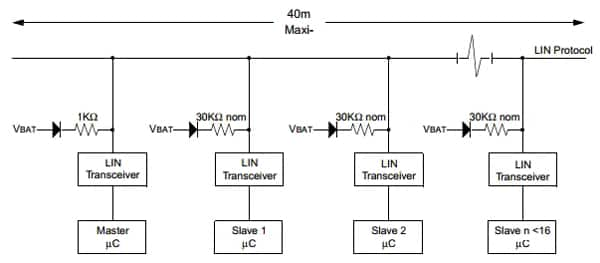
The bus uses a single wire pulled high through a resistor with open collector drivers. A dominant state is signaled by a ground level on the bus and occurs when any node pulls the bus low.
Typically, the microcontroller is isolated from the bus levels by a line driver/receiver. This allows the microcontrollers to operate at 5 V levels, while the bus operates at higher levels.
The MCP2021 from Microchip provides a physical interface between a microcontroller and a LIN half-duplex bus with output +3.3 V at 50 mA with a turn-off voltage of 2.5 V, making it feasible to power from an energy-harvesting source. It is intended for automotive and industrial applications with serial bus speeds up to 20 Kbaud. With a half-duplex, bi-directional communications interface between a microcontroller and the serial network bus, it translates the CMOS/TTL logic levels to LIN-level logic, and vice versa.
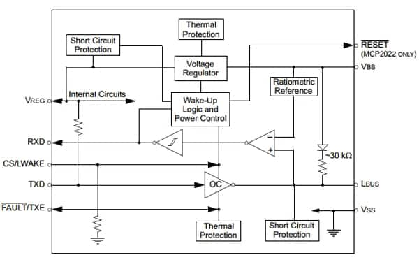
The LIN specification 2.0 requires that the transceiver(s) of all nodes in the system be connected via the LIN pin with a maximum external termination resistance load of 510 Ω from the LIN bus to battery supply. This 510 Ω corresponds to one Master and sixteen Slave nodes.
The Master controls the bus by polling Slaves to share their data with the rest of the bus. Slave nodes only transmit when commanded by the Master, which allows bi-directional communication without further arbitration.
The bus protocol is relatively simple. A message transfers start with the Master issuing a synch break, followed by a synch field and a message field. It also sets the clock for the entire bus by transmitting a synch field at the beginning of each message, which is used for clock synchronization. Each Slave must use this synch byte to adjust its baud rate.
The synch break is held for 13-bit times, followed by a stop bit, and this lets the Slaves know that a message is coming. The Master and Slave clocks may have drifted as much as 15%, so the synch break may be received by a Slave as few as 11 bit times, or as long as 15 bits.
The second byte of each message is an Ident byte, which tells the bus what data will follow and indicates which node should answer and how long the answer shall be. Only one Slave may respond to a given command.
Slaves only transmit data on the bus when directed by the Master. Once the data is on the bus, any node may receive that data. Therefore, communication from one Slave to another does not have to be directed through the Master.
CAN
The CAN protocol provides a more complex network capability. Alongside the CAN protocol itself, the conformance test for the CAN protocol is defined in the ISO 16845, which guarantees the interchangeability of the CAN chips.
CAN is based on the “broadcast communication mechanism”, which is based on a message-oriented transmission protocol. It defines message contents rather than stations and station addresses. Every message has a unique message identifier that defines the content and the priority of the message. This is important when several stations compete for bus access.
As a result of the content-oriented addressing scheme, a high degree of system and configuration flexibility is achieved. It is easy to add stations to an existing CAN network without making any hardware or software modifications to the existing stations as long as the new stations are purely receivers. This allows for a modular concept and permits the reception of multiple data and the synchronization of distributed processes, ideal for easily adding new energy-harvesting nodes. Data transmission is not based on the availability of specific types of stations, which allows simple servicing and upgrading of the network.
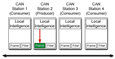
The identifier of each message specifies the priority of a message, and these are configured during system design in the form of corresponding binary values and cannot be changed dynamically. The identifier with the lowest binary number has the highest priority.
Bus access conflicts are resolved by arbitration of the identifiers involved by each station observing the bus level bit for bit. All the nodes with recessive transmission and dominant observation lose the competition for bus access and automatically become receivers of the message with the highest priority, not re-attempting transmission until the bus is available again.
Transmission requests are handled in order of their importance for the system as a whole. This proves especially advantageous in overload situations. Since bus access is prioritized on the basis of the messages, it is possible to guarantee low individual latency times in real-time systems.
The CAN protocol supports two message frame formats, the only essential difference being in the length of the identifier. The “CAN base frame” supports a length of 11 bits for the identifier, and the “CAN extended frame” supports a length of 29 bits for the identifier.
Detecting and signaling errors
Unlike other bus systems, the CAN protocol does not use acknowledgement messages. Instead, the protocol signals errors immediately as they occur. For error detection, the CAN protocol implements three mechanisms at the message layer 2 level.
Cyclic Redundancy Check (CRC) safeguards the information in the frame by adding a frame check sequence (FCS) at the transmission end. At the receiver, the FCS is re-computed and tested against the received FCS. If they do not match, there has been a CRC error.
The frame check verifies the structure of the transmitted frame by checking the bit fields against the fixed format and the frame size, while receivers of a message acknowledge the received frames. If the transmitter does not receive an acknowledgement, an ACK error is indicated.
The CAN protocol also implements two mechanisms for error detection at the physical bit layer. The first is monitoring, where each station that transmits also observes the bus level and detects differences between the bit sent and the bit received. This permits reliable detection of global errors and errors local to the transmitter.
The second technique is bit stuffing, where the coding of the individual bits is tested at bit level. The bit coding used by CAN is "Non Return to Zero (NRZ)" coding, and the synchronization edges are generated by means of bit stuffing. After five consecutive equal bits, the transmitter inserts a ‘stuff’ bit into the bit stream that is removed by the receivers.
If one or more errors are discovered by at least one station, the current transmission is aborted by sending an "error frame". This prevents other stations from accepting the message and ensures the consistency of data throughout the network. After transmission of an erroneous message that has been aborted, the sender automatically re-attempts transmission (automatic re-transmission). Nodes may again compete for bus access.
However, one defective station can lead to all messages (including correct ones) being aborted, and this requires self-monitoring of the bus. The CAN protocol provides a mechanism to distinguish sporadic errors from permanent errors and local failures at the station by statistical assessment of station errors. This recognizes a station's own defects, and can put the station into different operating modes including powering down, so that the rest of the CAN network is not affected.
CAN in Automation
The CAN in Automation (CiA) group was founded in 1992 to provide technical, product, and marketing information for the use of CAN in industrial automation applications. The group now includes over 560 companies. It developed the CANopen specification as a higher layer protocol for embedded networks with highly flexible configuration capabilities. CANopen was designed for motion-oriented machine control networks, such as handling systems. Now it is used in a wide range of applications such as medical equipment and building automation.
The aim is to abstract the CAN-specific details such as bit-timing and implementation-specific functions. It provides standardized communication objects for real-time data and configuration data, as well as network management data. Standardized CANopen device and application profiles simplify the tasks of integrating a CANopen system with off-the-shelf devices, tools, and protocol stacks.
The TJA1051 from NXP Semiconductors is a high-speed CAN transceiver that provides an interface between a Controller Area Network (CAN) protocol controller and the physical two-wire CAN bus.
The transceiver is designed for high-speed (up to 1 Mbit/s) CAN applications, providing differential transmit and receive capability to a microcontroller with a CAN protocol controller.
It offers improved Electromagnetic Compatibility (EMC) and Electrostatic Discharge (ESD) performance, and also features ideal passive behavior to the CAN bus when the supply voltage is off, reducing the current and power consumption. The TJA1051T/3 and TJA1051TK/3 can also be interfaced directly to microcontrollers with supply voltages from 3 V to 5 V.
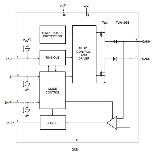
The TJA1051 also has a Silent mode. This combines the functionality of the previous generation devices with improved EMC and ESD handling capability. Improved slope control and high DC handling capability on the bus pins provides additional application flexibility.
The TJA1051T/3 and TJA1051TK/3 allow for direct interfacing to microcontrollers with supply voltages down to 3 V for connection to an energy-harvesting source. The TJA1051T/E allows the transceiver to be switched to a very low current Off mode, where the entire transceiver is disabled, allowing the microcontroller to save power when CAN communication is not required. The bus pins are floating in Off mode, making the transceiver invisible to the rest of the network.
Energy management
The CBC-EVAL-09 from Cymbet is a thermal energy generation evaluation board that provides a Peltier effect device to drive a data converter and network link, integrating the DC-DC converter needed to provide the power. EnOcean’s EDK312C-RF evaluation kit also uses thermal energy to power the data conversion and link, with output voltage between 3 and 4 V, facilitating a new generation of 3 V transceivers.
The operation of these devices starts at typical 20 mV from a 2 Kelvin temperature difference using a standard low-cost Peltier element. The output power is in the range from μW to mW and depends on the actual temperature difference at the Peltier element.
Power management devices are vital for delivering the power harvested from the environment in a usable manner. The bq25504EVM from Texas Instruments is the first of a new family of intelligent integrated power management solutions that can be used in network nodes that use energy harvesting.
The bq25504 manages the microwatts (µW) to milliwatts (mW) of power generated from a variety of DC sources, such as thermal electric generators, through a highly efficient boost converter/charger. This requires only microwatts of power to begin operating and once started extracts power from low voltage output harvesters such as thermoelectric generators (TEGs), or single or dual cell solar panels. The boost converter can be started with an input voltage as low as 330 mV, and once started, can continue to harvest energy down to 80 mV.
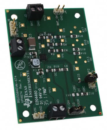
The bq25504 supports a variety of energy storage elements to capture the energy that is harvested and provide the higher current required by the transceivers. Preventing damage to the storage element and the CAN or LIN transceiver is also vital, so in the bq25504 both maximum and minimum voltages are monitored against undervoltage (UV) and overvoltage (OV) levels. The device toggles the ‘battery good’ flag to signal an attached microprocessor when the voltage on an energy storage battery or capacitor has dropped below a pre-set critical level to prevent the system from entering an undervoltage condition.
Conclusion
While connecting wired networks using energy harvesting as a source of power may be a niche application, the falling voltages and power consumption of new devices open up the possibilities of removing the power lead from CAN and LIN network nodes. With more efficient energy harvesting sources and power management devices, 3 V transceivers can now be supported, providing new design options for industrial networks and reducing power and installation costs.

免责声明:各个作者和/或论坛参与者在本网站发表的观点、看法和意见不代表 DigiKey 的观点、看法和意见,也不代表 DigiKey 官方政策。


 中国
中国