Hall-Effect Sensing Provides Current Measurement for the Smart Grid
投稿人:DigiKey 欧洲编辑
2015-10-20
Efficient operation of the smart grid relies on the ability to measure current levels and other parameters at high resolution. A further key feature of smart-grid applications is the increased use of small-scale renewables. These systems demand the use of inverters to convert the electricity captured from solar or wind sources to an AC signal compatible with grid distribution. Electrical current sensors are needed in the control loop to ensure that these conditions are satisfied. This article looks at the Hall-effect technology for current sensing and how it can be applied to the smart grid.
The smart grid relies on accurate real-time data to ensure that the equipment that controls power delivery, and which interfaces to the grid, is kept running at peak efficiency. The data captured by sensors on the grid can spot potential trouble spots forming and alert operators to the problem or activate functions that can perform remedial action. This is leading to the installation of power distribution units (PDUs) that perform accurate measurements of delivered power and its characteristics.
A key additional feature of smart-grid applications is the increased use of small-scale renewables. These systems demand the use of inverters to convert the electricity captured from solar or wind sources to an AC signal compatible with grid distribution. The AC must be synchronized to the grid and have low harmonic distortion but this can be challenging to achieve.
In the case of photovoltaics, an inverter is required to convert the DC generated by each of the cells to a suitable AC power output. Electrical current sensors are needed for the inverter’s control loop in order to ensure proper connection to the grid. The sensors must accurately measure both AC and DC currents and have good dynamic performances. Very fast response time is required to react quickly to any change in the grid and shut off or disconnect the system before damage occurs. A high output bandwidth enables the system to measure high frequency AC currents and harmonics in order to ensure that the delivered power meets the stringent targets for power quality imposed by the electricity suppliers.
The ability to recognize DC outputs to the grid is also important. Regulations differ from country to country but the limits are typically small: on the order of tens to hundreds of milliamperes. Current sensing can also support failure detection, checking for short-circuits and overload conditions.
Although a number of current-sensing options exist, sensors based on the Hall effect provide a combination of features that are highly suited to these applications, including voltage transient survival, current inrush handling, space constraints and modularity. The technology can support contactless sensing, ensuring intrinsic isolation and protection against large voltage transients and inrush currents.
Named for Edwin Hall, who discovered the effect in 1879, it is the production of a voltage difference across an electrical conductor or semiconductor by a magnetic field that is perpendicular to a current flow in a nearby conductor. The voltage produced depends on the material used in the receiving conductor and the applied magnetic field, which is itself dependent on the aggregate current flow in the source conductor.
The voltage difference is caused by charge carriers being deflected from a straight path by the magnetic field. Electrons build up along one face of the receiving conductor to produce a measurable voltage difference. The resulting electric field opposes the migration of further change so that a steady electrical potential can be maintained as long as the charge carriers continue to flow through the material.
One drawback of Hall-effect sensors for current-sensing applications has been their accuracy limitations in terms of the zero ampere output voltage as well as changes in sensitivity with temperature. Other issues have been output signal bandwidth and output noise. Newer generations of Hall-effect devices have dealt with these issues, providing components that are better suited to inverter-monitoring applications and power monitoring in general.
Allegro Microsystems has employed a BiCMOS process to support accurate amplifier design with digital circuitry for factory programming of the gain and offset over temperature. Both the Hall element and the amplifier are chopper-stabilized for better accuracy and offset drift performance.
The Allegro ACS756 family of current sensor ICs uses these techniques, combining precision, low-offset linear Hall sensor circuit with a copper conduction path located near the die to provide high accuracy. Applied current flowing through this copper conduction path generates a magnetic field which is sensed by the integrated Hall IC and converted into a proportional voltage. A response time of less than 4 μs allows sensing of current in higher-frequency switching inverters. In applications that work at lower frequencies, such as those required for grid monitoring, the output can be filtered to lower the noise on the output and improve the resolution.
The internal resistance of the conductive path is 130 µΩ typical, providing low power loss. The thickness of the copper conductor allows the device to survive up to five-fold overcurrent conditions. The terminals of the conductive path are electrically isolated from the sensor leads. This allows the ACS756 family of sensor ICs to be used in applications requiring electrical isolation without the use of opto-isolators or other costly isolation techniques.
Asahi Kasei’s CQ-3301 is a high-speed current sensor based around an ultra-thin film indium arsenide quantum-well technology and a coreless package to provide a space-saving VSOP24 option. Designed to allow the current to pass through the package in applications such as inverter monitoring, the device has an isolation voltage of 3.0 kV over 60 seconds assuming 50/60 Hz AC in the primary conductor, and a response time of 0.5 µs. With a low-noise output of 1.6 mVRMS, the CQ—3301 offers low temperature drift for sensitivity and zero-current output. It complies with the IEC/UL-60950 and UL-508 safety standards.
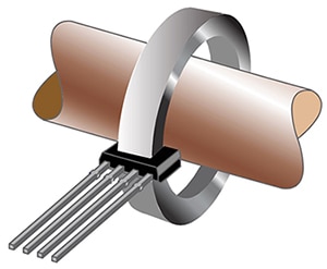
For very high-current applications, Allegro offers the A136x family of sensor ICs. Each is packaged in a 1 mm-thick SIP able to fit in the gap of a C-core around a conductor. The devices, such as the A1363, can sense currents of more than 1500 A. They offer a 120 kHz bandwidth, suitable for high-frequency inverters, again providing better accuracy through output filtering for lower bandwidths, such as those expected of grid-monitoring designs.

Figure 1: The SIP-packaged A136x from Allegro can be mounted in a C-core for measuring current levels in a high-voltage conductor.
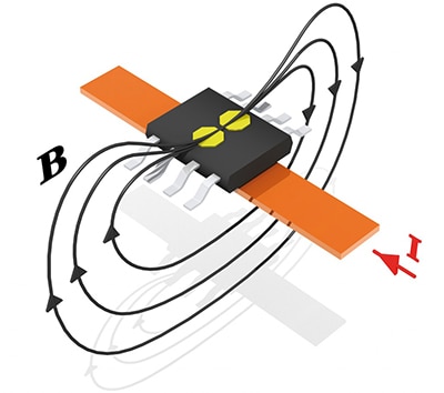
The Triaxis current-sensing technology developed by Melexis, used in products such as the MLX91205 has allowed the company to develop a series of surface-mount packages that can sit over the conductor embedded in a PCB or a bus-bar instead of having it pass through the package. As conventional Hall-effect sensors are sensitive to magnetic fields perpendicular to the chip surface rather than parallel to have an accurate measurement from a device placed over a PCB trace or bus-bar, the field needs to be made locally vertical. This is what the Melexis Integrated Magnetic Concentrator (IMC) technology is designed to do.
IMC uses highly permeable, low-coercive-field, amorphous ferromagnetic layer, which is bonded directly onto the Hall-sensor chip’s surface, focusing the magnetic field flux lines onto Hall that are about one-tenth the size of the ferromagnetic element. The two parts of the IMC collect and amplify the small magnetic flux parallel to the chip surface and locally rotate the in-plane component into a magnetic field perpendicular to the chip’s surface.

Figure 2: The Melexis IMC technology concentrates field lines to allow sensing of the perpendicular field when the sensor is mounted over the bus-bar or PCB trace.
The sensor’s current range is limited by the geometry of the conductor and the shield. The current range may be increased easily by increasing either the cross-section of the bus-bar or the distance between the sensor and current conductor. The sensor can monitor currents from 5 A to 100 A on PCBs or up to 1000 A on bus-bars. There are two different product versions available. The 91205HB features a linear magnetic field range of ±25 mT and the 91205LB handles a linear range of ±10 mT.
As a result, offering the possibility of non-contact sensing, Hall-effect devices provide versatile solutions for current monitoring in smart-grid applications, whether for inverters in renewables or diagnostics in power-distribution units.

免责声明:各个作者和/或论坛参与者在本网站发表的观点、看法和意见不代表 DigiKey 的观点、看法和意见,也不代表 DigiKey 官方政策。


