Distributed Power Architecture (DPA) Choices Using Power Modules
投稿人:电子产品
2012-03-06
What once was a straightforward act of transforming an AC waveform into a DC source to power downstream devices (such as to modular DC/DC power converters at the load), is now greatly affected and driven by the power grid to maximize its available power. Power factor and harmonic correction (PFHC) must be implemented and are even regulated internationally.
We will first discuss the various types of distributed power architecture (DPA), from traditional to newly improved, and then present the latest AC/DC power “brick” solutions. We will then look at the Intermediate Bus Architecture (IBA) and compare the two.
A “tried and true” traditional DPA places modular DC/DC converters within mere inches of the load in order to maximize speed and efficiency and prevent instabilities due to stray impedances in longer lines running on a PC Board (PCB) or within a chassis.
The AC/DC portion of the power supply was typically mounted elsewhere, closer to the AC line input, power ON-OFF switch, fuses and any line filters that may have been needed. Later on when power factor correction became necessary, this function was usually integrated into the AC/DC chassis mount module.
This architecture is good for most applications, but where physical size is an issue, there are better alternatives in the power “brick” (Figure 1).

A slightly better idea
Many modular power “bricks” contain power factor and harmonic correction and are small enough that they can now be screw-mounted onto a PCB (such as the CUI VSBU-120-48) close to the DC/DC module. This architecture helps eliminate the longer power interconnections between the devices and reduces the footprint of the traditional solution. Some external passives might be needed with this architecture, a small price to pay for shrinking the old footprint of the larger chassis-mounted AC front-end solutions (Figure 2).

In addition, more efficient cooling can be achieved, sometimes without fans, because localized heat sinks, Peltier coolers and the system chassis can now be used with a thermal connection against the “brick” baseplate.
An even better solution
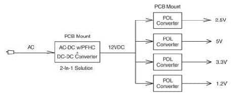
Now, power supply companies have integrated the AC/DC with power factor and harmonic correction plus the DC/DC point of load (POL) into a module. The best feature here is that they are now in “brick” sizes and sub-‘brick” sizes, thus saving considerable space over older architectures. These are sometimes called 2-in-1 architectures and are usually off-board. The TDK Lambda Americas DSP series is this type of converter, but has an added feature of being DIN rail-mounted (Figure 3).

This type of AC/DC converter is well-suited for distributed power architectures where POL converters are needed.
Telecom and communications changes
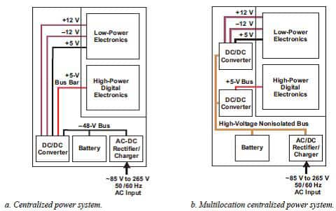
Back in the 1960s, telecom and datacom systems used centralized power supplies, typically located in the bottom of a rack or cabinet, including an AC/DC front-end rectifier/charger, a power backup battery, and a DC/DC converter. Large and costly supply bus bars routed the required voltages to each shelf inside the cabinet, which contained replaceable line cards with switching, diagnostic, and monitoring equipment. Figure 4 shows typical configurations of centralized power systems that were dominant until the mid-1980s.

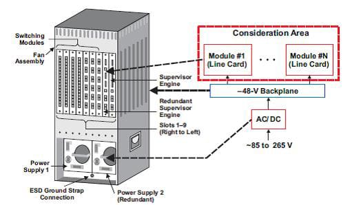
Enter the 1990s — telecom and datacom made significant architecture changes in the power system. The bulky centralized power supply was replaced by an AC/DC front-end power supply that provided a –48 V backplane voltage to each shelf and individual PC card (Figure 5).

Using a regulated bus architecture
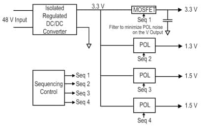
Within the realm of DPA, we can have an isolated, regulated DC/DC converter bus implementation module right after the AC/DC converter with power factor and harmonic correction module and, next in line, the multiple POL converter modules. Typically a 3.3 or 12 V output bus is chosen to drive the POL modules, typically with a 48 V input. In the case of a 3.3 V regulated bus structure, the highest power and current demand is on the 3.3 V supply rail, while the other bus voltages have lower power demands. There will also be some sort of sequencing requirement on the multiple POL modules that will be supplied by a device such as TI’s UCD90120. If the 3.3 V power must also drive POL, then a series MOSFET switch must be used to make sure the 3.3 V bus is active to all the POL’s before individual outputs are turned on. A capacitor right after the MOSFET helps minimize POL noise on the 3.3 V supply (Figure 6).

Using an unregulated bus architecture
In an unregulated bus architecture (Figure 7), we have the same output voltages as the previous example in Figure 6, but in this case 3.3 V is not the dominant load; all the POL voltages have significant current demands. In this case the 12 V bus is used and is unregulated. This 12 V choice is a desirable standard output voltage compromise that is low enough to keep the input/output differential across the POL buck module for efficient power conversion (using an adjustable supply to power the inputs of the POL devices can enable the designer to set a voltage lower than 12 V, if needed, for even better efficiency).

Systems with a large number of output voltages tend to use the unregulated bus architecture. The additional cost and size of the Intermediate Bus Converter (IBC) can be spread out across the greater number of output voltages. To illustrate an example, Figure 6 is a regulated bus and uses three POL modules; whereas Figure 7, the unregulated bus, uses four POL modules, a 33 percent increase. But in a system with six output voltages, the number of POL modules is six and seven, respectively, for the two architectures, an increase of only 16 percent in the number of POL modules needed.
The intermediate bus architecture (IBA)
Due to developments in the analog and digital IC industry, with an increasing number of low-level supply voltages in the 0.5 to 3.3 V range, in the early 2000s the market adopted the IBA. In many applications, the IBA-based power system includes a front-end AC/DC power supply with a typical output of 24 V or –48 V. In some data-communications and medical equipment, the input DC voltage can be from a 400 V power-factor-corrector block. This voltage is supplied to an IBC that provides isolation and conversion to the lower-level intermediate bus voltage, typically 5 to 14 V. This intermediate bus voltage is supplied to non-isolated, POL regulators that provide high-quality voltages for a variety of digital and analog electronic blocks. Figure 8 shows the trade-offs between the DPA and IBA.
| System Requirement | IBA | DPA | |
| Input-Voltage Range | Wide | — | Best |
| Narrow | Best | — | |
| Number of Outputs | <4 | — | Best |
| ≥4 | Best | — | |
| One Regulated Output Demands Most of the Power | — | Best | |
| Hybrid system could be the best in such case | |||
| Cost | Best | — | |
| Efficiency | Better | Best | |
| Load Supply - Voltage Quality | Best | Good | |
| Power Density | Best | Good | |
A complete analysis is needed
While we have examined the various types of distributed power architectures in an earliest-to-newest fashion, it is important to keep in mind that one approach is not necessarily better than the other. Instead, the lesson to be learned here is that for many cases the choice of which approach to use requires a complete and complex analysis. For more information, consult the references listed below and also the links provided to product pages on the DigiKey website.
References
- TDK-Lambda Americas, “Advantages of AC-DC “Brick” Power Modules.
- Texas Instruments, “Power-Management solutions for telecom systems improve performance, cost, and size” by Brian C. Narveson and Adrian Harris.
- Texas Instruments, “Improving System Efficiency with a New Intermediate-Bus Architecture” by Rais Miftakhutdinov.
免责声明:各个作者和/或论坛参与者在本网站发表的观点、看法和意见不代表 DigiKey 的观点、看法和意见,也不代表 DigiKey 官方政策。


 中国
中国