Dimming LEDs with Traditional TRIAC Dimmers
投稿人:电子产品
2011-07-19
TRIAC dimmers are designed for resistive loads such as incandescent or halogen lights and have a significant installed base in the United States and worldwide. Unfortunately, these phase-controlled dimmers are not readily compatible with LEDs since LEDs do not appear as a resistive load. Therefore LED-based solutions using traditional LED drivers will not perform as expected with TRIAC wall dimmers.

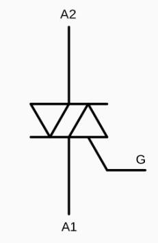
Figure 1: A TRIAC circuit symbol.
The TRIAC is a semiconductor triode that features two terminals and a gate. It may help to think of the TRIAC as two silicon controlled rectifiers (SCRs), which are a type of thyristor, placed back to back. A typical SCR has four layers of alternating P-type and N-type semiconductor material.
An SCR turns off when no current is flowing through it, and it can be switched on when a current is applied to its gate. An SCR conducts current in a single direction, but a TRIAC can conduct current in either direction, which is why a TRIAC looks like two SCRs.
Because TRIACs turn off when there is no current flowing through them, they’ve been popular household dimming solutions during the incandescent age. TRIAC dimmers took advantage of alternating current (AC) sine waves, which have zero voltage twice during each cycle. In the United States, there are 60 such cycles per second, so that the TRIAC turns off 120 times each second.
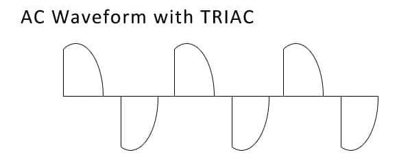
A firing capacitor being charged from a variable resistor often serves to apply a charge to the TRIAC's gate turning it back on. When a wall dimmer is turned low, it slows the current flow through the variable resistor and therefore takes more time to charge the firing capacitor and turn the TRIAC on again, effectively chopping the ac sine wave (Figure 2).

Figure 2: The TRIAC effectively chops the AC sine wave and reduces the amount of current reaching the light bulb.
In a traditional incandescent bulb, the pulsing current would cause the light to dim. It is important to note that the amount of current being sent to the load — for example, the light bulb — varies not just between on and off; there is a sloped increase toward the end of each half cycle, so cutting the AC sine curve limits the lighting to the a luminous phase of each cycle. Because LEDs are not a pure resistive load, there are at least two problems for LED-based incandescent bulb replacements.
First, the LED may not dim as expected since LEDs are either on or off, so light levels may not change as users anticipate or the light may flicker. Second, the 120-Hz flicker that TRIAC dimmers produce may shorten an LED’s usable life.
Fortunately, there are several LED driver solutions that bridge the gap between incumbent TRIAC dimmers and LEDs. The LED drivers will dim better using pulse width modulation, where the flow of power to a load is rapidly turned on and off, but without any sloped increase or decrease in current.
Examples of LED drivers that allow for TRIAC dimming include National Semiconductor's LM3450 and the Texas Instruments TPS92210. Typically, these types of LED drivers will receive the sinusoidal current from the TRIAC dimmer and manipulate it to produce smooth, flicker free LED dimming that does not affect reliability or durability.
Specifically, the LM3450 offers both power factor control and phase dimming decoder functions in a single device. The LM3450 LED driver interprets phase dimming from TRIAC wall dimmers and provides a corresponding pulse width modulation waveform.
The TRIAC dimmer decoder, according to National Semiconductor, detects the dimming angle of a rectified AC current. The LM3450 then decodes the dimming angle, filters it, and remaps the line to a 500-Hz pulse modulation waveform capable of properly dimming an LED.
National Semiconductor also employs a dynamic hold circuit on the LM3450 that helps to prevent the phase dimmer from misfiring. According to National Semiconductor, "both the dynamic hold and the decoder are sampled synchronously to reduce the overall efficiency drop due to the additional hold current. When a decoding sample period occurs, the dynamic hold is activated to ensure a proper angle is decoded. Because of this sampling method, non-sampled cycles will potentially cause the phase dimmer to misfire but should not affect the output LED current regulation. Finally, the dynamic filter and variable sampling rate provide fast, smooth dimming transitions."
免责声明:各个作者和/或论坛参与者在本网站发表的观点、看法和意见不代表 DigiKey 的观点、看法和意见,也不代表 DigiKey 官方政策。


 中国
中国