Development and Evaluation Boards for Serial Sensor Systems
投稿人:Convergence Promotions LLC
2012-11-15
Sensors work best when they are close to what they sense. The farther away they get, the higher the levels of induced noise and the more the signal can be degraded by cabling effects.
Increasing signal strength with amplifiers and buffers can let otherwise low-level signals transit longer runs cleanly. On the down side, this can use higher levels of power and radiate EMI and RFI depending on the signal or cable characteristics.
An alternate approach is to make the sensor a digital subsystem unto itself and use serial communications techniques to allow it to travel cleanly and cheaply. As either a state machine or under direction of an embedded controller, the digitalization of sensor information can mean a central collection point can reliably collect data distributed on a local board or over a vast area or volume of space.
This article looks at serial sensors and subsystems that we design engineers have at our disposal and some of the development and evaluation kits available to support them. It examines the transducer types available and the A/D converter subsystems used for serial transmission of typically short-reach analog data. It will discuss off-the-shelf solutions and the advantages they possess over one another. All parts, training material, data sheets, demo, evaluation and development kits mentioned here are available online at the Digi-Key website.
Hot or cold serial
Hot-powered, high-speed serial interfaces like USB have not typically been used for low-cost embedded sensor arrays, but that is changing. USB has been used when a higher-end machine like a laptop or tablet that has a USB port is the host. But even then cable lengths are limited to a few meters and USB ports are typically more costly and harder to implement than the lower-cost serial buses. Both master and slave side ports typically need a higher-end embedded MCU with a lot of code and memory space.
Now many microcontroller manufacturers provide good MCUs with USB support, and USB connectivity is increasingly being used for gathering data from sensors. Especially nice is the fact that USB is a powered port with a tree structure, so a local USB link from a host can go to a hub, which allows several sensors to all connect, all with distributed power from the tree. In addition, low-cost USB-to-RS-232 adaptors allow sensor links from the hub to transit long distances at low cost.
Development kits using USB can implement this hub as a reference design, allowing it to be a platform for rapid prototyping and testing. An application example of a system that may benefit from USB is a high-speed accelerometer; an example of a USB-based development platform is the Freescale TWR-SENSOR-PAK. While this kit is aimed at supporting the company’s MC9S08QE96CLK (a Digi-Key non-stocking part) and MC9S08JM60CLD microcontrollers, like many other kits it provides reference designs, software examples, and application notes, paving the way for us to use the kit as an advanced starting point, in this case for accelerometer, pressure, and touch-based applications.
But for most engineers, serial sensor buses will use lower-cost signaling levels, and they will design sensor systems that implement either state machines or embedded MCUs as monolithic modules that perform the basic tasks of sensor interfacing and communications.
Fortunately, several wired serial standards are popular and are used for distributed and remote sensor interfacing. Some are proprietary to a specific company and their products and are not as popular as the industry standard parts, but these may still be appropriate solutions in some designs.
A case in point is the MICROWIRE™ protocol developed by National Semiconductor for use with its COPS™ family of processors. This simple short-reach, three-wire interface has been adopted by a few companies who still offer solutions based on the MICROWIRE interface.
MICROWIRE has some nice features and may be an ideal solution for some needs. It is fairly fast (Mbit/sec transfer rates) and has very little overhead with no device addressing built in. Instead, each device needs a chip select if it shares the same clock.
In addition, MICROWIRE has a separate data line in (SI) and data line out (SO). As a bi-directional interface, it requires three wires, but when used in a write-only application, such as a display, you can eliminate the third wire. The same is true for a read-only application like a simple sensor.
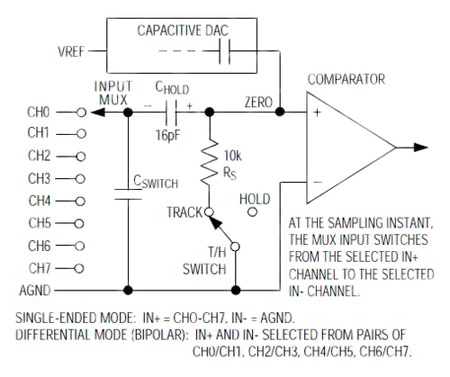
A few key manufacturers support MICROWIRE and have some nice sensor and data acquisition subsystems with pretty good performance. Take for example the Maxim MAX192BEWP+ . This 5 V serial A/D subsystem provides 10-bit resolution at 133 kHz conversion rate. Housed in small 20-pin SO and SSOP packages, the MAX192 has an on-chip 8-channel analog multiplexor that can be used for eight single-ended or four differential sensors (see Figure 1). A high bandwidth track-and-hold circuit is also inside. If used with line drivers, this allows a remote sensor accessed over a long-run serial line to switch in calibration references or monitor several sensors over a single communications link.

Another nice feature is the low-power (1.5 mA) operation with 2 µA draw during power down. An SHDN/pin puts it into low-power mode, and the part can be shut down between conversions to draw around 10 µA average current.
To hedge their bets, many device makers will support more than one serial protocol standard on a specific chip, and that is what Maxim does on these parts. In addition to supporting MICROWIRE, the Max192 also supports the SPI protocol, and it has a special interface for the Texas Instruments TMS320 DSP devices. The MAX188DCPP+ supports these protocols as well as QSPI and provides a 12-bit accuracy pin-compatible upgrade.
Another dual-mode MICROWIRE and SPI-based sensor comes from Microchip Technology with its TC77-3.3MCTTR temperature sensor IC. This part has a measurement range from –55 to +1250C and is packaged in a small SOT-25 package. Running from 2.7 to 5.5 V, the +/-3 degree accurate sensor uses an internal Sigma Delta converter. The low-cost PICtail TC77DM-PICTL is a small demo/evaluation board for the TC77 parts that uses a SIP through-hold connector for easy prototyping. It adds a small PIC micro on board.
Note that National Semiconductor, now part of Texas Instruments, still supports MICROWIRE with temperature sensors and evaluation boards. The LM95071CIMF/NOPB is a 2.4 to 5 V temperature monitoring IC in an SOT23-5 package that has a sense range from –40 to +1500C. It uses a 13-bit Sigma Delta converter to achieve a +/1 degree sensitivity over MICROWIRE and SPI. Likewise the LM95071EVAL/NOPB PowerWise temperature sensor evaluation board lets you test and evaluate this technology quickly and easily.
SPI for high speed
SPI has been the ideal choice for many short-reach serial sensor subsystems. This is partly because it is such a widely used and deployed standard, supported by virtually every MCU manufacturer, partly because of its fairly high-speed data rates and partly because of its individual and daisy-chaining modes of operation.
Like MICROWIRE, SPI is a Master/Slave architected protocol. It can be used as a single master/slave using three wires or as a master with many slaves using four wires per device; the fourth is a select line, in this case the SS signal.
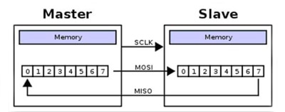
The definable polarity of the SCLK clock signal from the master clocks the MOSI data out line from the master into the slave. Like a circular buffer, the MISO data returns to the master. Only devices with its SS select line held low will respond (see Figure 2).

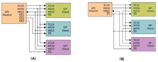
But with multiple slaves, the MISO pins needs to be tri-state since they all connect together (see Figure 3A). Using a cascaded approach lets sensors connect in a loop-type fashion where the data out from one becomes the input to the next stage. All are enabled and selected and clocked in common (see Figure 3B).

Many advanced SPI data acquisition and sensor interfaces are readily available, including some that are really fun to play with. Take for example the Analog Devices ADIS16209CCCZ inclinometer and accelerometer. This SPI-accessible sensor and digital sensor interface is part of the company’s inertial sensor ‘iSensor technology’. It has a 0.1-degree-accurate inclination sensor with a 0.025 degree resolution and a +/-1.7 G acceleration range at 0.244 mg resolution. Digital control of sample rate and frequency response is programmable, as are alarm thresholds and limits. The Analog Devices ADIS16209/PCBZ is an evaluation board that lets you test and evaluate this technology quickly and reliably.
Another cool SPI-accessible sensor function from Microchip Technology is the TUNAG001 MEMs magnetic compass module. This 3-axis magnetometer has a built in tri-axial accelerometer which can calculate its position relative to terrestrial magnetism and outputs its direction in degrees. A gyroscopic output is also in there.
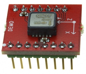
The Murata Electronics SCA3100-D04 PCB is another 3-axis accelerometer module that can be OEM’ed or prototyped. Packaged in a 16-pin DIP (see Figure 4), the 3.3 V +/-2G high-performance accelerometer is based on the company’s 3D MEMs technology and is highly stable (+/-30 mg offset stability over temperature range (-40 to +1250C)). While aimed at automotive applications such as suspension control and roll-over detection, these parts are effective for any inertial and motion detect-and-control applications. These parts also exemplify the philosophy of integrating an entire mixed-signal subsystem on-chip through the use of a serial interface for complete access and control (see Figure 5). A training overview of the company’s automotive sensing technologies can also be viewed online at Digi-Key’s website.


I²C a major player
Another serial bus that has gained inroads into the data acquisition world is the Inter Integrated Circuit (I²C) protocol developed by Phillips (now NXP Semiconductors). This Master/Slave 2-wire protocol uses clock and data in parallel to all connected devices. Each chip has fixed chip addresses with variable sub addresses to allow more than one of the same devices on the serial network.
I²C is not as fast as SPI, but is still very useful for many types of sensor applications. Many signals do not need to be sampled and converted at high sample rates. Real-time means “fast enough to handle the application at hand,” not necessarily fast.
Another key factor is that the I²C protocol is so simple that a state machine can be at the heart of the chip instead of a microcontroller. This allows the logic to get small and compact while eliminating a lot of clocking sources and digital noise. A prime example of this is the Atmel ATAVRSBPR1 Pressure One Sensors Xplained development board (see Figure 6), a barometric pressure-sensor application based on Bosch Sensortec’s Piezoresistive MEMs BMP085 Digital Barometric Absolute Pressure Sensor.

The Bosch sensor connects via I²C to provide information that an embedded controller can use to detect altitude, rate of rise or fall, weather forecasting, and other atmospheric information. A temperature sensor is also on-chip and can be used to compensate the pressure sensor’s output.
This small daughter board is part of the company’s Sensors Xplained series for the Atmel family of microcontrollers. A family of mother boards can be used to test and develop applications with the Atmel family of sensors and processors.
Another useful I²C interface is the Vishay Semiconductors VCNL4000-GS08 Proximity and Infrared ambient-light sensor (see Figure 7). Ambient-light sensors are making inroads into handheld equipment to save energy on backlights when they are not needed. In addition to just sensing a level, this part has a built-in IR LED and photo-pin diode to detect proximity such as closing a cell phone for example, which can also save power as well as the need for a mechanical switch.

The I²C port on this part can run from 1.7 to 5 V, meaning that low-voltage implementations do not need level shifting. Programmable LED drive currents are from 10 to 200 mA in 10 mA steps and 16-bit effective resolutions are achieved for ambient-light levels as well as proximity detection. The Vishay Semiconductors VCNL4000 development kit can be used to test and evaluate the I²C-based ambient light and proximity sensors.
The Honeywell Microelectronics HMC6343 3-axis compass chip is an advanced I²C sensor application based on the Honeywell Anisotropic MagnetoResistive (AMR) technology. Ideal for measuring heading, pitch, and roll, the 9 x 9 mm monolithic device has very low cross-axis sensitivity, enabling it to measure both the direction and magnitude of the earth’s magnetic field. A training module on the company’s magnetic sensors is online at Digi-Key.
This 36-pin LCC part is actually a sensor and microcontroller in one. Intended for use as an independent subsystem, it communicates with a host microcontroller through its I²C bus. This approach allows these complex functions to be implemented quickly and painlessly as a pre-engineered OEM solution. The Honeywell Microelectronics HMC6343-EVAL board implements this in a through-hole DIN 100-mil-spaced module. The board can be used for testing or OEM’ed for small-volume designs.
Navigating another way
In addition to physical navigation and movement in space, user interface navigation is also a prime area for I²C based sensors. One example is the Knowles Acoustics KJ-33000-003 I²C MEMs Joystick Controller (see Figure 8).

This part provides X-axis and Y-axis justified position data when read over the I²C port. It can be written to as well put into sleep mode to save power. The Knowles Acoustics KJ-33000-002 development module is available for testing and development and features the part in an encapsulated housing that provides connectivity access.
Touch-screen controllers have also found the I²C serial protocol an ideal way to provide user interface and navigation with very few wires and minimized I/O requirements from an embedded MCU.
Several manufacturers provide I²C touch-sensor interfaces such as the Texas Instruments TSC2007IYZGT, a 4-wire analog resistive touch-screen sensor interface with 12-bit resolution and an I²C interface. The TSC2007EVM board is TI’s demonstration and evaluation board supporting this part.
Another touch interface controller, this one for capacitive touch systems, is the Atmel AT42QT2160-MMU with support for buttons and sliders. The I²C port runs from 1.8 to 5 V, enabling it to be used with very low-voltage interfaces.
The Atmel EVK2160A is an evaluation kit for this part that demonstrates the PCB layouts and use for 16 keys or two 8-key sliders. It is based on the company’s Qmatrix technology which uses spread-spectrum transverse-charge transfer-sensing electrodes, resulting in small Touch pads.
There are over two dozen I²C-based touch solutions from eight suppliers on Digi-Key’s site, so check Digi-Key’s parametric search engine to find the best ones suited for your needs.
Conclusion
Serial sensors can provide a high level of functional density and performance in a small size. Whether state machine driven or transparently implemented with an embedded MCU inside, the ability to send analog information in digital format with as few connections as possible increases reliability, lowers cost, and creates more elegant solutions.
Low-cost and off the shelf development and evaluation systems for serial sensors are readily available for a variety of sensor types and serial buses. These serve well as a reference design, an OEM solution, or as a rapid prototyping aid to evaluate a new technology.
Digi-Key is your source for parts, data-sheets, training materials, and development boards with many suppliers and solutions for sensor-system designs.

免责声明:各个作者和/或论坛参与者在本网站发表的观点、看法和意见不代表 DigiKey 的观点、看法和意见,也不代表 DigiKey 官方政策。


