Design Considerations for Selecting Capacitors for DC Link and Inverter Applications
投稿人:DigiKey 北美编辑
2016-05-13
Thanks to advancements in power semiconductor technology and circuit topology refinements, today’s inverters and switching power supply circuits are delivering incrementally higher performance than ever. Efficiencies have improved, standby power usage is well into the green energy zone and physical circuit sizes are shrinking. Even life expectancy has been enhanced.
Behind this performance push is a changing application landscape. Smaller power supplies and inverters are a better fit for shrinking consumer and industrial products. Inverters, once limited in market scope, are now at the core of every solar, wind and water power system, as well as in UPS devices, portable power sources and more. Additionally, in many critical applications, product reliability is paramount.
While most of the credit for these improvements rightfully goes to the semiconductor manufactures and their applications engineers, there have also been significant advancements in capacitor technology. For many years, aluminum electrolytic capacitors have been a mainstay of power-supply designs, and they are still the best choice for many applications.
Although we haven't seen any revolutionary leaps in aluminum electrolytic technology, there has been a lot of technology creep over the years. This creep has made them physically smaller, more reliable and available with lower ESR- and ripple-current ratings. The latter two are of particular importance for any power circuit that employs DC link circuitry. Of course, that includes switching power supplies and inverters.
Power metalized film capacitors are advancing even faster than electrolytics. We've seen evolutionary improvements in film material, metallization and the overall device construction. While metalized power film and electrolytic capacitors have some application overlap, each has situations in which they are best suited. Furthermore, film capacitors are available in a much broader range of form factors and terminations.
This article will address practical issues that can influence the choices you make for capacitors in DC link applications. Engineers generally strive to select the best circuit components consistent with functional and cost requirements. After the calculations have been done for the basic electrical requirements, there are still a lot of possible choices for device selection. Within that range, there may not be a "wrong" choice, but there are certainly good, better and best choices. The best choices will have a meaningful impact on physical size of the finished circuit, cost, power efficiency and reliability. Since capacitors are the components that can have the shortest expected lifespan, improvements in this area can result in a much more reliable end product.
The Basics
DC link (also called buss link) circuits are used primarily to balance the instantaneous power variations between the input source and the output load or a power circuit (Figure 1). In the example of a switching power supply, AC power is converted to DC without passing through a transformer, and fed to a high-frequency power oscillator. The DC link capacitor is applied from positive to negative after rectification. In a power inverter, a DC link capacitor is placed in parallel with the input to minimize the effects of voltage variations as the load changes. The DC link capacitor also provides a low-impedance path for ripple currents generated by power switching circuits.
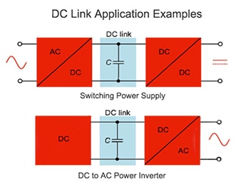
Figure 1: In a switching power supply, the DC link capacitor is placed across the positive-to-negative rails after rectification (top). In a DC to AC power inverter it is placed in parallel with the input (bottom). (Image courtesy of DigiKey)
As designers opt for higher-frequency switching power circuits to reduce transformer size, the spikes generated by the power device (switching on and off) need to be more effectively decoupled. To minimize heat and best protect the power devices, DC link capacitors need to have very low equivalent series resistance (ESR) and low self-inductance. The other critical performance specification is ripple-current.
Understanding Specifications
Some of the specifications associated with capacitor selection can be confusing, even if you have a basic understanding of what the terms mean. However, that's still a good place to start. We know that for DC link applications, capacitors should have very low ESR, low self-inductance and high ripple-current ratings. So let's take a closer look at each.
Depending on the active circuit in which it is applied, a capacitor also has characteristics of a resistor and an inductor. The ESR is the sum of all the internal resistances of a capacitor at a specified frequency and temperature. Like a resistor, its unit of measurement is ohms. So, not surprisingly, self-inductance is measured in the same units as an inductor. In this case, nano Henries (nH).
So far this is pretty straightforward: some parameters such as ESR should be lower, others, like ripple-current tolerance, should be higher. Ripple current is the total amount of RMS alternating and direct current that a capacitor can withstand, under specific conditions, without causing it to fail.
Like ESR, ripple-current must be defined for a specific frequency and temperature range. While the EIA has established a standard for expressing these specifications, not all capacitor manufacturers follow the standard. So you may find yourself considering two different manufacturers’ parts with no direct way to make an apples-to-apples comparison. If you find yourself in this situation, the easiest solutions are to request that the “odd” manufacturer supply you with a comparable spec or move on to another vendor.
Aluminum Electrolytic Capacitors
Aluminum electrolytics, or "lytics" as they are commonly called, are a good fit for many inverter applications. They typically have several times the power density of film caps. That makes them well suited for applications requiring high capacitance to handle peak load requirements and voltage ride-though (when there is a momentary dip in voltage level). These applications include UPS units and motor drives. Cornell Dubilier Electronics has a series of suitable electrolytics that works well in many DC link applications. A good example is the low-ESR AFK Series, featuring a maximum ESR at 100 kHz and 20˚C that ranges from 1.350 Ω down to 0.033 Ω (Figure 2.) It also has a high tolerance for cold, with an operating temperature range of -55˚C to 105˚C. The maximum ripple current at 100 kHz and 105˚C can range from 90 mA to 2.060 A.
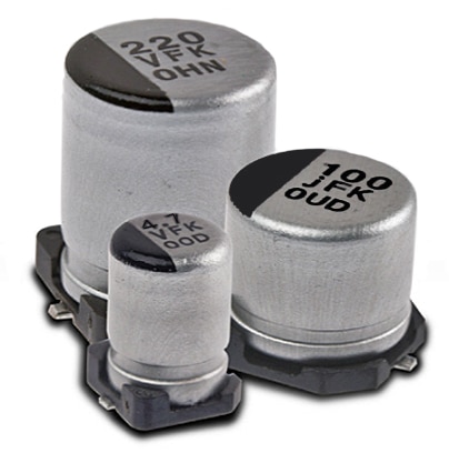
Figure 2: For lower-voltage, board-level designs, the CDE AFK Series features a maximum ESR that ranges from 1.350 Ω down to 0.033 Ω (at 100 kHz and 20˚C.) It also has a high tolerance for cold, with an operating temperature range of -55˚C to 105˚C. (Image courtesy of Cornell Dubilier Electronics)
Lytics generally cost less than film capacitors, but are not available for bus levels exceeding 550 VDC. Therefore, it becomes necessary to configure the caps in series to reach the required working voltage. Depending on the operating conditions, lytics will typically have a much shorter lifespan than film caps. This is because in aluminum electrolytics, the cathode of the capacitor is a liquid electrolyte. The anode is the aluminum foil. Over time, the electrolyte gradually evaporates, reducing the capacity of the device. This is why lytics are often over-specified on capacitance, effectively extending their lifespan.
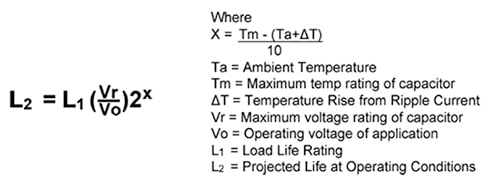
Equation 1: Formula for computing operational life of aluminum electrolytics. (Source: Illinois Capacitor)
As noted, because of the liquid electrolyte, all aluminum electrolytic capacitors dry out over time, thereby losing capacitance and weakening performance specs. This makes it especially important to buy capacitors from reliable sources such as authorized distributors. When you buy from a non-franchise source, you may be buying products that are near or past their date code. Like grocery products, the "sell-by date" assures you of getting a fresh product. These date codes are not always easy to decode. A franchise source will provide assurance that the capacitors you are purchasing are fresh and not counterfeit.
Metalized Film Capacitors
While metalized film capacitors are more expensive than lytics, and are not as high capacity, they have a number of significant advantages in many DC link circuit applications. For example, they are lower in ESR and have low self-inductance. They can tolerate power surges without damage to performance and have superior self-healing properties. Unlike aluminum electrolytics, which have an actual aluminum foil winding, metalized film caps are constructed with an ultra-thin layer of metal that has been vapor-deposited onto the surface of a film substrate. If a short circuit should occur between film layers, the high energy stored between layers and the thinness of the metallization combine to create a corrective flash that vaporizes the fault in less than 10 µS. This action is so fast and requires so little energy that the performance of the capacitor remains essentially unchanged.
Illinois Capacitor's PHC Series is a good example of an axial-lead film capacitor well suited for DC link applications (Figure 3.) In addition to low ESR (2.4 to 12.9 mW at 100 kHz and 25˚C) and high maximum ripple current (up to 14 A at 100 kHz), it's axial-leaded design works well in circuits having point-to-point wiring.

Figure 3: Illinois Capacitor's PHC Series has low ESR, high maximum ripple current, and an axial lead design that makes it suited to point-to-point wiring. (Image courtesy of Illinois Capacitor)
A different approach is taken in Cornell Dubilier Electronics 947D Series (Figure 4). Also designed for inverter/DC link circuits, it offers a very robust package design with screw terminals. ESR is as low as 0.9 mW at 100 kHz with ripple current ratings in the 62 to 101 A range at 100 kHz.
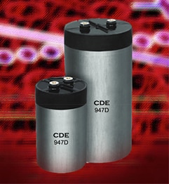
Figure 4: CDE's 947D Series has very high ripple current making it a good match for inverter designs for wind, solar, fuel cells, UPS systems and more. (Image courtesy of Cornell Dubilier Electronics)
Other benefits of film capacitors are:
- Physically smaller in size than electrolytics
- Wider temperature range
- Non-polarized
- Virtually unlimited shelf life and much longer operational life
- Able to greatly increase estimated operational life by derating
While electrolytics typically are available in a cylindrical package with choice of wire lead, snap-mount or screw terminations, film capacitor specifiers have a much greater choice. These include round and box types, with terminations designed to direct mount to specific types of power semiconductor devices, while others use multiple leads for highest reliability in PCB mounting. Potential benefits include ease of mounting, increased current capacity, improved mechanical stability and product reliability.
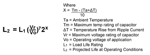
Equation 2: Formula to estimate lifespan for metalized film capacitors, which have a much longer lifespan than classic electrolytics, note exp. 7. (Source: Illinois Capacitor)
The company notes that operating conditions affect the life of a film capacitor in a very similar manner to aluminum electrolytic capacitors. However, voltage derating has a greater effect on the life as compared to an aluminum electrolytic capacitor.
Conclusion
Selection of the best capacitor for a power inverter or other DC link application usually begins with a comparison of the required capacitance and ripple currents. Make sure that the specs you are comparing are referenced to the same operational standards. When starting with an application circuit from a semiconductor manufacturer, stay with the recommended dielectric technology, as different circuit topologies may not match well to different capacitor technologies. Depending on voltage and capacitance requirements, compare costs for minimum ripple current needed for the expected product lifetime. If planning to use multiple electrolytics to meet a voltage requirement or multiple film capacitors to meet a capacitance need, consider all associated costs. Also look at differences in physical packages and termination needs.

免责声明:各个作者和/或论坛参与者在本网站发表的观点、看法和意见不代表 DigiKey 的观点、看法和意见,也不代表 DigiKey 官方政策。


 中国
中国