Data Logging for IoT: Analyzing the Environment for More Stable and Efficient Systems
投稿人:DigiKey 北美编辑
2017-03-28
This is the fourth part of a series of articles (see “Scoping an Arduino-Based Irrigation Project”) using an example smart irrigation project to explore the types of questions and design issues most real-world control systems, especially IoT systems, need to address.
As the numbers of connected devices that smart applications use increases, particularly the addition of sensors and actuators, the complexity of keeping the system stable and operating efficiently also increases. This complexity is further amplified when the devices are geographically widespread and the environmental conditions may differ significantly.
To mitigate potentially widening disconnects between the user’s strategic assumptions and the dynamically changing tactical needs of the system, designers need to more deeply explore data logging and analytics. However, not all data is good data, and as the IoT takes hold, developers and designers need to be discerning to avoid data overload.
This article will define three types of data and how to apply them in an irrigation application, but it can be useful for any smart building or industrial application. The core tenets are the same. It will then introduce a controller that can be used in a distributed intelligence architecture, describe its salient attributes with respect to the application, and outline how to get up and running with it.
Smart system data types
Smart systems can support centralized analytics or perform local analysis by handling three types of data: planning, reference, and operational data. Figure 1 shows a block diagram that places the connected controllers and different types of data in relation to each other.

Figure 1: Block diagram showing the three types of data – planning, reference and operational – and their relationship with the various connected controllers within a smart irrigation system. (Diagram drawn using DigiKey’s Scheme-it®)
While it makes sense for the system controller to be a single point of access for the planning and reference data, it may make more sense for the system controller to distribute some of that data to the connected devices to support local decision making for larger installations.
The user inputs the planning data into the system. This includes configuration settings, device topology, algorithm selection, and scheduling information. This article calls these types of information planning data because it documents what the user wants the system to do. When there are discrepancies in this data, it is a flag for a potential problem between the user’s expectations and how the system is actually set up to perform.
In the context of an irrigation project, the configuration settings might include information about soil type, plant type, sprinkler type, and sun exposure. In contrast, a smart-building application might specify working hours and idle timeouts for environmental and lighting controls. These settings may affect the selection of algorithms. For simpler installations, the algorithms may remain static. More complicated installations can permit changing algorithms based on the weather pattern of the current season.
Documenting the topology of the connected devices may enable synergy between adjacent stations so that they can take advantage of the operation of each other. For example, in irrigation, knowing that it is windy might afford some efficiency by irrigating starting from the upwind stations and working downwind with the understanding that the delivered moisture may bleed from one station to the next, resulting in shorter watering times.
Plan versus execution
Reference data consists of historical and forecast data that provides a baseline for any follow-up analysis of the system’s performance. The historical data can be stored in a locally or remotely accessed database depending on its size and complexity. The forecast data provides the basis for predicting what environmental changes the system may need to respond to in the short term. If there is little-to-no deviation in the forecast data to the historical data, then the system is probably going to perform as expected. However, there is a good chance there will eventually be deviation between the operational data and the historical or forecast data, and that this deviation will increase over time. As this occurs, the operator needs to re-evaluate the planning data to better accommodate those differences.
The easiest way to acquire historical data is to collect the operational data and store it for future reference. This provides the most value when the operational environment experiences a regular cycle of changes, such as a changing of the seasons, while the plant and soil mixture remain stable.
Access to accurate forecast data of how the environment will change supports the highest efficient operation of a smart system. For smart irrigation systems, there are a number of weather forecast services available for reference. These companies combine access to a large network of weather stations with an extensive database of weather information to provide the most relevant information for where the irrigation system is located. For smart building applications, an example of accessing forecasting data is when the system integrates with the meeting scheduling systems, such as for conference rooms.
Operationally tie it together
The operational data represents the heart of the data logging activity, and it associates the two other types of data with the tactical reality of the here and now. The active algorithms will be making resource and actuator decisions based on the collected sensor data. In larger installations, it may make sense to also store the collected sensor data for later analysis.
The process of logging the collected sensor data enables the production and validation of consumption reporting. Consumption reporting lets the user know how much the system is improving efficiency and determine whether it is delivering the value that justified installing it in the first place.
Data logging also enables the comparison with historical data to improve the system’s ability to detect when a problem is beginning to manifest as early as possible. If the problem has been experienced before, then the historical data already includes the behaviors leading up to the problem, allowing the system to recognize it earlier. If the problem has not been experienced before, the operational data will show a deviation from the expected behavior that should flag the operator to investigate why there is a discrepancy.
Flexibility via local memory
There are several methods to perform data logging. One method is to pool all of the collected data in a central controller while the system is operating. One problem with this method is that data can be lost if the communication between the connected devices breaks down for any reason while the system is operating.
A more robust way to log data for a geographically distributed application is to collect and store the data locally at each connected device and then transmit it to the central controller at a later, more convenient time. This not only disconnects the primary operation of the system from supporting the analytics function, but it keeps the communication lines between the stations open for dedicated operations or data logging, as appropriate.
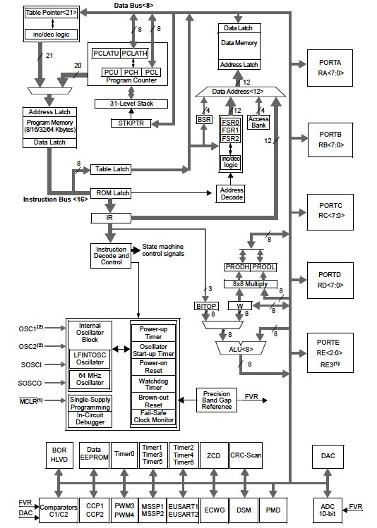
Microchip Technology’s PIC18F46K40 microcontrollers (MCUs) provide sufficient processing and communication performance, as well as large enough local memory to support connected devices for irrigation projects of most sizes. The MCUs support a number of options including 40-pin PDIP or UQFN packages, and can run at up to 64 MHz to provide 16 MIPS. They include up to 64k bytes of program flash, 3728 bytes of data SRAM, and 1024 bytes of data EEPROM memory (Figure 2).

Figure 2: The PIC18F46K40 MCUs from Microchip Technology are a good choice for processing the inputs and data for the irrigation project. They also have high-endurance non-volatile memory, Microchip’s XLP low-power technology, and peripherals that run independent of the core processor. (Image source: Microchip Technology)
The flash cells for the program memory are rated for up to 10,000 erase/write cycles. The controller can write to its own program memory space under internal software control. A boot loader routine located in the protected boot block makes it possible for a connected device to update itself in the field. This enables the system to easily update the irrigation/evaporation algorithms it uses so that they always benefit from and incorporate the latest lessons learned. The large program memory supports splitting the program flash in half to support safe field updates.
The data EEPROM is rated for up to 100k erase/write cycles. The large and high endurance non-volatile memory permits the system to safely collect and store a wide range of data. The large data memory enables each controller to manage and store the data for an expanded set of sensors. It also enables the system to store and retain the data locally for a longer period of time because multiple generations of operational data can reside in the data memory at the same time.
These microcontrollers feature Microchip’s eXtreme Low-Power (XLP) technology that supports a typical sleep current as low as 50 nA at 1.8 V. While the system may provide power via lines, this allows the installation to extend the life of any battery-powered backup for each connected device. The Core Independent Peripherals are able to handle their tasks with no code or supervision from the microcontroller CPU to maintain operation.
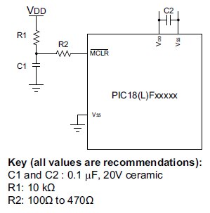
Microchip’s PIC18Fxxxxx microcontrollers are able to operate with a minimum set of connections and external components (Figure 3). All the VDD and VSS pins must be connected. If the power traces run longer than six (6) inches in length, then the design should use a tank capacitor to supply the local power source. The designer should determine the size of the tank capacitor based on the trace resistance that connects the power supply source to the device, and the maximum current drawn by the device while the application is running.

Figure 3: Diagram of the recommended minimum connections to use the Microchip PIC18F46K40 microcontroller. (Image source: Microchip Technology)
In addition to the power supply pins, the designer must connect the MCLR pin (Master Clear) so that the microcontroller can support Device Reset and Device Programming and Debugging. It may be beneficial to add the shown components to help increase the application’s resistance to spurious Resets from voltage sags. The specific values of R1 and C1 will need to be adjusted based on the application and PCB requirements. Any components associated with the MCLR pin should be placed within 0.25 inch (6 mm) of the pin.
If the microcontroller will be supporting in-circuit serial programming and debugging, the PGC and PGD pins (not explicitly shown in Figure 3) must also be connected. Keep the distance between the connector and pins as short as possible. Pull-up resistors, series diodes, and capacitors on these pins are not recommended as they will interfere with the programmer/debugger communications to the device. However, if they’re required in the final design, they should be removed during programming and debug.
Conclusion
Developers of electronic and embedded systems in the age of IoT are increasingly required to understand and optimize data. However, knowing that not all data is necessarily good data, getting the right data is critical to improving the efficiency of a system.
This article has discussed acquiring and applying three types of data: The planning data tells the system how the user thinks the system is configured and how it should operate. The reference data provides the system with a basis for how the system is expected to behave. Lastly, the operational data closes the control loop so that the user and system can compare and analyze the system’s actual behavior with its expected behavior to find opportunities for improving stability and increasing efficiency.
With a distributed processing approach using low-power MCUs, designers can balance processing power with low power, as well as cost. The PIC18F46K40 is one such MCU. In addition, it has sufficient, non-volatile memory to collect, maintain, and use data. It also helps that the MCU can offload some peripheral functions from the main processing unit to reduce latency and improve overall system efficiency.

免责声明:各个作者和/或论坛参与者在本网站发表的观点、看法和意见不代表 DigiKey 的观点、看法和意见,也不代表 DigiKey 官方政策。


