


Current Source Enables Linear Regulators to Deliver Lower Output Voltages
投稿人:电子产品
2013-10-01
Traditionally, due to architectural dependence on reference voltage, a linear regulator’s output voltage is limited to the reference voltage. Consequently, because older generation architectures employ 1.2 V as reference, the minimum output voltage of these regulators is limited to 1.2 V. Today, ICs on system boards need much lower voltages to operate. Hence, these linear regulators cannot power such ICs that require less than 1.2 V and much higher current.
However, a novel linear-regulator architecture overcomes this low output-voltage limitation. By replacing the conventional voltage reference with a current source, the new-generation linear regulators can deliver output voltages much below 1 V. In fact, it has the ability to go as low as zero volts, according to the maker. Additionally, this new linear regulator architecture can also be configured as a current source. Also, unlike older generation linear regulators, it can be paralleled to provide higher output currents, if needed.
Adjustable regulator
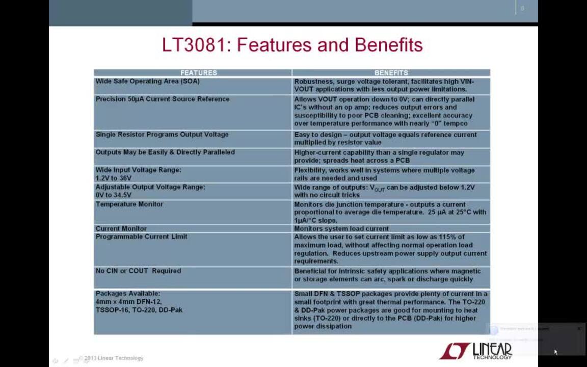
Linear Technology’s LT3081 and LT3082 incorporate the new architecture to deliver new levels of performance with adjustable output voltage that can be programmed down to 0 V at high current. While LT3081 is rated for 1.5 A output current capability, the LT3082 is a 200 mA low-dropout linear regulator.
As shown in Figure 1, a precision 50 μA reference current source connects to the non-inverting input of a power operational amplifier. The power operational amplifier provides a low-impedance buffered output to the voltage on the non-inverting input. A single resistor from the non-inverting input to ground sets the output voltage. If this resistor is set to 0 Ω, zero output voltage results. Therefore, any output voltage can be obtained between zero and the maximum defined by the input, which in the case of LT3081, is 40 V maximum. The Table lists many common output voltages that can be generated using the closest standard 1% resistor values for RSET.

| VOUT (V) | RSET (kΩ) |
| 1 | 20 |
| 1.2 | 24.3 |
| 1.5 | 30.1 |
| 1.8 | 35.7 |
| 2.5 | 49.9 |
| 3.3 | 66.5 |
| 5 | 100 |
Table: RSET values for common output voltages.
Unlike the bootstrapped reference in older regulators, the internal reference current source of the new regulator allows the regulator to have gain and frequency response independent of the impedance on the positive input, according to the datasheet. In comparison to the older adjustable regulator like the LT1086, wherein loop gain changes with output voltage and bandwidth changes if the adjustment pin is bypassed to ground, LT3081’s loop gain is unchanged with output voltage changes or bypassing, according to the LT3081 datasheet.
As described, the linear regulator’s output regulation is not a fixed percentage of output voltage, but is a fixed fraction of millivolts. Use of a true current source allows all of the gain in the buffer amplifier to provide regulation, and none of that gain is needed to amplify the reference to a higher output voltage. As a result, the LT3081 achieves unmatched line and load regulation of less than 2 mV, independent of output voltage.
The LT3081 has many additional features that facilitate monitoring and control. Current limit, which is accurate to ±10%, is externally programmable via a single resistor between the ILIM pin and OUT. A resistor placed between ILIM pin and OUT on the LT3081externally sets current limit to a level lower than the internal current limit. The value of this resistor is calculated as RILIM = ILIMIT/400 mA/kΩ + 400 Ω. Shorting this resistor out disables all output current to the load, therefore only bias currents remain.
Similarly, the IMON pin produces a current output proportional to load current. For every 1 A of load current, the IMON pin sources 200 μA of current. This can be sensed using an external resistor to monitor load requirements and detect potential faults. Because this pin can operate at voltages above OUT, it operates even during a short-circuit condition, as per the description in the datasheet.
Current source
For applications that need a current source, the LT3081 can be easily configured as a 2-terminal current source using just two resistors, as shown in Figure 2. The figure shows the connections and basic formulas to calculate the values of the external resistors based on the output current requirements. The 50 μA reference current from the SET pin is used with one resistor (RSET) to generate a small voltage (VSET), usually in the range of 100 mV to 1 V. This voltage is then applied across a second resistor (ROUT) that connects from OUT to the first resistor. Per discussion in the datasheet, 200 mV is a level that rejects offset voltage, line regulation, and other errors without being excessively large.

Also, as per the description, the programmable current limit and current-monitoring functions are often unused in a current-source configuration. In that case, the manufacturer recommends tying IMON pin to OUT and leaving ILIM pin open. However, the TEMP pin is still available for use. However, if unused, it is recommended to tie TEMP to OUT.
Input or output capacitors for stability are optional in either linear regulator or current-source mode of operation. However, if you prefer to use an output capacitor in linear-mode operation, the manufacturer recommends using 10 μF with an ESR of 0.5 Ω or less to provide good transient performance.
Paralleling linear regulators
The linear regulator LT3081 is rated for a maximum output current of 1.5 A. If your application requires higher output current, it can be obtained by paralleling two or more LT3081s together. In that case, as shown in Figure 3, tie the individual SET pins together and the individual IN pins together. The outputs are connected in common using small traces of printed circuit board (PCB). These PCB traces function as ballast resistors to promote equal current sharing. LT3081’s datasheet shows that PCB trace resistance is mΩ/inch. In other words, ballasting requires only a tiny area on the PCB.

Since the worst-case room temperature offset between the SET and the OUT pins is only ±1.5 mV, the circuit allows the use of very-small ballast resistors, as shown in Figure 3. As depicted, each LT3081 uses a 10 mΩ ballast resistor. Using this value, better than 80% equalized sharing of the output current can be achieved, according to the maker. However, the designer must note that the external resistance of 10 mΩ (5 mΩ for the two devices in parallel) adds about 15 mV of output regulation drop at an output current of 3 A. That means, if the output voltage were as low as 1 V, this would drop regulation by 1.5%.
If this increase in load regulation from the ballast resistors is unacceptable, the manufacturer recommends using IMON output to compensate for these drops. In the applications section of the datasheet, the manufacturer describes load current sharing without ballasting.
In short, linear regulators using current-source reference give designers a new device that is capable of delivering adjustable output voltage over a very wide range beyond the ability of traditional linear regulators. Plus, they are versatile as they can be configured as a current source or paralleled for higher output current.
免责声明:各个作者和/或论坛参与者在本网站发表的观点、看法和意见不代表 DigiKey 的观点、看法和意见,也不代表 DigiKey 官方政策。


 中国
中国