Comprehensive Guide to Thermostat Wire Types, Applications, and Wiring Techniques

作者:Syston Cable Technology

Thermostat wiring plays a crucial role in controlling and automating HVAC (Heating, Ventilation, and Air Conditioning) systems in both residential and commercial settings. This article explores the common types of thermostat wires – specifically 2-core, 3-core, 4-core, 5-core, 6-core, 8-core, and 10-core thermostat wires. The differences in core types will be examined along with their compatibility with various thermostats and the recommended wiring techniques for effective temperature control. Additionally, an explanation the O/B wire’s role and the essential preparations needed before wiring will be presented. By providing a detailed understanding of thermostat wires, this article aims to serve as a technical guide for HVAC professionals, electricians, and DIY enthusiasts.

What is thermostat wire?

Thermostat wire is a low-voltage cable, typically ranging from 18 AWG to 24 AWG, designed to handle signal connections for HVAC systems. Unlike power cables, thermostat wires do not carry high voltage; instead, they transmit control signals between the thermostat and the HVAC system. These wires are insulated and are often bundled in different core configurations to serve various functions, such as powering the thermostat, controlling heating and cooling units, and operating fans.

Types of thermostat wires: core differences and applications

The number of cores in a Syston thermostat wire directly affects its functionality and compatibility with different thermostats. Here’s a breakdown of common thermostat wire types and their applications:

2-core thermostat wire (Figure 1)

  • Functionality: Primarily used for basic heating-only systems
  • Application: Suitable for simple systems without the need for cooling or fan control. A two-core wire typically includes a "R" wire (power) and a "W" wire (heat)
  • Limitations: Lacks the versatility for controlling cooling systems or more complex HVAC setups. Ideal for single-stage heat-only systems

Image of typical 2-core thermostat cableFigure 1: Typical 2-core thermostat cable. (Image source: Syston)

3-core thermostat wire (Figure 2)

  • Function: Adds a common (C) wire for continuous power
  • Application: Typically used in systems that require power for digital thermostats but only control heating. Suitable for smart thermostats with basic power needs
  • Wiring: Consists of "R" (power), "W" (heating), and "C" (common)
  • Limitations: No control over cooling or fans, limiting it to basic heating applications

Image of typical 3-core thermostat cableFigure 2: Typical 3-core thermostat cable. (Image source: Syston)

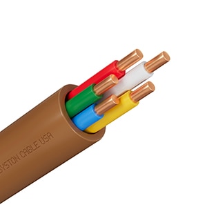
4-core thermostat wire (Figure 3)

  • Functionality: Suitable for heating and cooling systems
  • Application: A 4-core wire includes "R" (power), "W" (heat), "Y" (cooling), and "G" (fan). This configuration is commonly used for basic HVAC systems that require both heating and cooling
  • Limitations: Limited to simple two-stage systems; does not support advanced features like additional fan speed control or zoning

Image of typical 4-core thermostat cableFigure 3: Typical 4-core thermostat cable. (Image source: Syston)

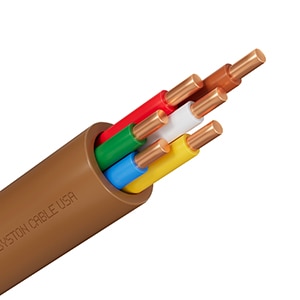
5-core thermostat wire (Figure 4)

  • Function: Adds a common (C) wire for continuous power alongside heating, cooling, and fan control
  • Application: Used with more advanced thermostats that require constant power for Wi-Fi and other smart features. Suitable for basic HVAC systems that support both heating and cooling
  • Wiring: "R" (power), "W" (heating), "Y" (cooling), "G" (fan), and "C" (common)
  • Limitations: Typically used for single-stage systems; does not support multi-stage or multi-zone setups

Image of typical 5-core thermostat cableFigure 4: Typical 5-core thermostat cable. (Image source: Syston)

6-core thermostat wire (Figure 5)

  • Functionality: Used for more advanced systems with additional control requirements
  • Application: In addition to the standard connections (R, W, Y, G), a 6-core wire may include "C" (common wire for continuous power) and an auxiliary wire such as "O/B" for controlling heat pumps
  • Limitations: Supports more complex setups but may still lack flexibility for multi-zone or multi-stage systems

Image of typical 6-core thermostat cableFigure 5: Typical 6-core thermostat cable. (Image source: Syston)

8-core thermostat wire (Figure 6)

  • Functionality: Suitable for complex, multi-stage HVAC systems
  • Application: Includes connections for two stages of heating (W1 and W2) and cooling (Y1 and Y2), as well as fan, power, and common wires. This wire is ideal for multi-stage systems where precise temperature control is required
  • Limitations: Not commonly used in residential settings due to increased complexity

Image of typical 8-core thermostat cableFigure 6: Typical 8-core thermostat cable. (Image source: Syston)

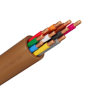
10-core thermostat wire (Figure 7)

  • Functionality: Designed for the most advanced HVAC systems
  • Application: With 10 cores, this wire supports additional features such as multiple heating and cooling stages, auxiliary heat, emergency heat, and multiple fan speeds. It is used in advanced systems, especially in large commercial HVAC setups
  • Limitations: Rarely used in standard home HVAC systems, as it requires a compatible advanced thermostat and a sophisticated HVAC setup

Image of typical 10-core thermostat cableFigure 7: Typical 10-core thermostat cable. (Image source: Syston)

What is the O/B wire?

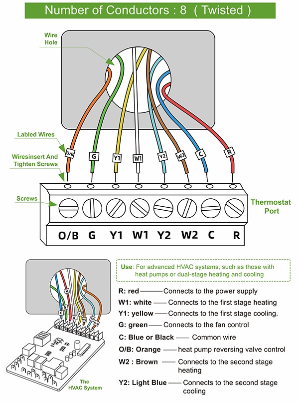
The O/B wire, often referred to as the reversing valve wire, is essential for heat pump systems (Figure 8). The O/B wire controls the reversing valve in a heat pump, which determines whether the system is in heating or cooling mode. In cooling mode, the O/B wire is energized to shift the valve to allow cooling; in heating mode, it is de-energized. This wire is usually connected to the thermostat’s O/B terminal, and the setup can vary depending on the manufacturer’s specifications.

Diagram of wiring designations for a heat pump thermostatFigure 8: Wiring designations for a heat pump thermostat. (Image source: Syston)

Applications of thermostat wiring

Thermostat wiring is essential for the following HVAC components:

  • Heating: Controls heating units such as furnaces and heat pumps
  • Cooling: Manages cooling devices, including central air conditioners
  • Fans: Controls the fan's speed and mode, allowing for efficient air circulation
  • HVAC Systems: Integrates heating, cooling, and ventilation into one control unit for seamless climate management

Thermostat wires are critical for managing these components, enabling users to maintain an ideal indoor environment and improve energy efficiency.

How to control cooling, heating, fans, and HVAC with thermostat wiring

Cooling: To control cooling systems, connect the “Y” wire from the thermostat to the HVAC cooling unit. The thermostat will activate the cooling system when the indoor temperature rises above the setpoint.

Heating: The “W” wire is connected to the heating unit. When the temperature drops below the desired level, the thermostat signals the heating system to turn on.

Fan Control: The “G” wire enables fan operation. The thermostat can control fan speed (if supported) to maintain consistent air circulation and ensure that heated or cooled air is evenly distributed.

Heat Pump Systems: For heat pump configurations, the O/B wire controls the reversing valve, allowing the system to switch between heating and cooling. This setup is commonly seen in areas with moderate climates, where heat pumps are effective for year-round comfort.

Preparing for thermostat wiring

Before beginning thermostat wiring, follow these preparatory steps:

Turn off power: Ensure that power is turned off at the breaker box to avoid electrical hazards. Thermostat wiring operates at low voltage, but accidental shorts can still damage equipment.

Check compatibility: Verify that the thermostat and HVAC system are compatible with the thermostat wire you are using. Not all thermostats support multi-stage wiring, and some may lack connections for additional cores.

Gather tools: Prepare tools such as wire strippers, a screwdriver, and electrical tape. A multimeter is also helpful for testing connections and ensuring proper wiring.

Identify terminals: Label each wire according to its function (e.g., R, W, Y, G) before disconnection. This step is especially useful when upgrading or replacing an existing thermostat.

Consult wiring diagrams: Always refer to the thermostat’s manual and HVAC wiring diagram to ensure correct connections. Incorrect wiring can lead to system malfunctions or damage.

Conclusion

Syston thermostat wiring is a fundamental part of setting up and operating HVAC systems. Understanding the differences in core types – from 2-core for simple heating to 10-core for advanced multi-stage setups – allows technicians and homeowners to choose the correct wire type for their specific needs. The O/B wire plays an essential role in heat pump systems, enabling users to switch between heating and cooling modes effectively.

By following proper wiring techniques and understanding the specific requirements of each thermostat and HVAC component, users can achieve efficient climate control in various settings. Ensuring compatibility, proper preparation, and accurate wiring will contribute to the optimal performance and longevity of HVAC systems.

免责声明:各个作者和/或论坛参与者在本网站发表的观点、看法和意见不代表 DigiKey 的观点、看法和意见,也不代表 DigiKey 官方政策。

关于此作者

Syston Cable Technology

Syston Cable Technology is an established American corporation that designs, manufactures, and sells high-speed electronic cables and low-voltage cables primarily used in dataComm, A/V, security, automation, and electrical markets. The company is headquartered in Chino, California. Their combined global team of employees, innovators, and technologists has empowered customers in all regions of the world to anticipate what’s next and push the boundaries of what’s possible. Syston Cable Technology operates on a promise of "superior quality, innovation, competitive pricing, and on-time delivery".