Charge Controller Design for Maximum Battery Lifetime in PV Systems
投稿人:电子产品
2012-09-05
For any complete energy-harvesting system designed to provide power to anything but small, short-duration loads, storage batteries represent a necessary but significant portion of the initial expense. The cost of batteries over the lifetime of the system can have an even larger impact if care is not taken to maximize the useful life of the battery component. What’s more, if unit growth continues for photovoltaic and other energy-harvesting systems relying on large-capacity storage batteries, designs that fail to maximize battery life could have a negative environmental impact due to the extra material and energy consumption needed to manufacture replacement systems as well as dispose of exhausted units.
Storage battery specifications such as robustness and projected lifetime depend, to a great extent, upon the chemistry of the cells; Li-ion, LiFePO4 and sealed lead acid are widely used battery chemistries. Most commercial Li-ion cells can now be charged to 4.2 V/cell. A LiFePO4 battery allows a much higher charge and discharge rate, but the energy density is lower. The typical cell voltage is 3.6 V. The charge profile of both Li-ion and LiFePO4 is preconditioning, constant current and constant voltage. For maximum cycle life, the end-of-charge voltage threshold could be lowered to 4.1 V/cell. Battery chemistry notwithstanding, there are several design criteria engineers should know that affect the life expectancy of any type of storage cell.
One of the most common battery killers is overcharging. Battery life is reduced when charging is continued for an excessive length of time or at too high a voltage. Simple charging circuits either exceed optimum charge voltages or make a trade-off for excessive charging cycle time. The particular chemistry determines the voltage level to use, and manufacturers provide detailed specs for charging and discharging voltages and rates.
A basic system with a photovoltaic panel for energy input provides either a blocking diode or switch in series with the battery to prevent draining the battery during periods of low light. To avoid overcharging, excess current can be shunted from the solar cell once the battery is fully charged. In practice, even this simplified design requires monitoring and control electronics.
Although those of us living in frigid climates tend to associate battery death with the coldest part of the year when your car won’t start in a blizzard, most battery damage actually can occur in hot weather. Temperature plays an important role in ensuring long storage battery life. All batteries depend on chemical reactions that are thermally activated. With strong temperature dependence, these reactions can get out of control, leading to sudden and serious damage. At low temperatures, battery electrolytes can also freeze when the charge is depleted. This is especially important in photovoltaic energy harvesting since the lowest temperatures are often coincident with the lowest solar energy levels (because the energy source is lost at night) compounding the detrimental temperature effect.
The bq24650 (Figure 1) from Texas Instruments is a versatile synchronous switch-mode battery-charge controller specifically targeted to solar power applications. The bq24650 offers programmable maximum power point tracking (MPPT) in a constant frequency PWM controller design for three phase charging – preconditioning, constant current, and constant voltage. Precharging is limited by an internal timer to a maximum of 30 minutes

Figure 1: TI bq24650 synchronous switch-mode battery charge controller designed for solar power applications.
The bq24650 switch-mode battery charge controller accepts photovoltaic panel voltages from 5 to 28 V and provides outputs to the battery of up to 36 V. It can be configured to operate in boost mode as well, although that is beyond the scope of this article.
The TI charge controller includes several key features that allow photovoltaic energy-harvesting-system designers to maximize battery life. The bq24650 includes common charge controller features such as settings for charge termination based upon maximum voltages to reduce problems related to overcharging as well as key safety features designed to maximize battery life.
When the input is powered by a solar panel, the input regulation loop lowers the charge current so that the solar panel can provide maximum power output. It also provides input voltage regulation, which reduces charge current when input voltage falls below a programmed level.
The bq24650 automatically restarts the charge cycle if the battery voltage falls below an internal threshold and enters a low quiescent current sleep mode when the input voltage falls below the battery voltage.
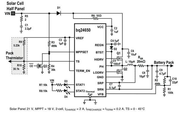
The part’s features and control inputs are perhaps easiest to understand by exploring the example design shown in Figure 2. A solar panel has a unique point on the V-I or V-P curve, called the maximum power point (MPPT), at which the entire photovoltaic system operates with maximum efficiency and produces its maximum output power. On the bq24650, the MPPT point is set through a resistor divider to keep MPPSET (pin 2) at 1.2 V. The following equation is used to set the MPPT point:
VMPPSET = 1. 2 V x (1+R3/R4)
Charging can be disabled by pulling MPPSET below 75 mV if other system monitoring is added around the basic charge controller design.
The charging voltage is programmed with the 2.1 V regulated output at the VFB pin. The battery voltage is set according to:
VBAT = 2.1(1 + R2/R1)

Figure 2: TI bq24650 typical application example.
On the input voltage regulation side, the bq24650 uses the simple constant-voltage algorithm for maximum power point tracking. The controller reduces the charge current to maintain the photovoltaic panel voltage for maximum power output.
The important design criteria to maximize battery life are controlling the charging current, limiting the voltage and ending the charge cycle at the appropriate time. Charging current is sensed by the voltage drop across a 20-mΩ resistor between pins SRP and SRN. Full-scale voltage is 40 mV between these two pins, so maximum charging current is set to 2 A in the design example.
With deep discharge cells in mind, the bq24650 will apply a precharge cycle to attempt to revive batteries that have discharged below a threshold, VLOWV. The internal timer will trigger a fault indication after 30 minutes if the precharge cycle is unable to raise the battery voltage beyond VLOWV.
If precharge conditions are met, the controller moves into the second phase of charging. During the “fast charge” cycle, the charging current is regulated. Charging is terminated when the voltage at the VFB pin exceeds the VRECH threshold and the charging current drops below 10 percent of the fast charge current.
The final safety net provided by the bq24650 design is temperature sensing. Thermal shutdown avoids potentially catastrophic events. It can also provide life insurance for the battery as the system ages after initial design parameters have drifted. Temperature sensing at the battery pack is enabled with a properly located and attached negative temperature coefficient thermistor. The bq24650 allows upper and lower safe temperatures to be programmed by the energy-harvesting-system designer. The bq24650 suspends the charge cycle for temperatures outside the designed range. Hot and cold limits are set through a resistive divider on pin TS between VREF and ground.
The part’s QFN package has low thermal impedance, which provides good thermal conduction from the silicon to the ambient, to keep junction temperatures low. As an added level of protection, the charger converter turns off and self-protects whenever the junction temperature exceeds the TSHUT threshold of 145°C. The charger stays off until the junction temperature falls below 130°C.
Designers should always study the manufacturer’s datasheet carefully, especially for this critical and non-trivial design step. For hands on assessment, the bq24650EVM is an evaluation module to assist users in evaluating the bq24650 synchronous battery charger. For more information on the bq24650 itself, use the link provided to access product pages on the DigiKey website. Also on the site, TI offers a useful Product Training Module entitled “Power Management for Energy Harvesting.”
免责声明:各个作者和/或论坛参与者在本网站发表的观点、看法和意见不代表 DigiKey 的观点、看法和意见,也不代表 DigiKey 官方政策。


 中国
中国