Calculating LED Junction Temperature in Lighting Applications
投稿人:电子产品
2011-06-07
Operating an LED above the maximum temperature recommended by the manufacturer can lower the device's efficiency and light output and can lead to premature failure. An LED's hotspot is defined as the junction between p- and n-type semiconductors that form the diode. This article uses an example lighting application to illustrate how to calculate the junction temperature of an LED and determine if it's likely to exceed the specified upper limit.
Calculating LED junction temperature
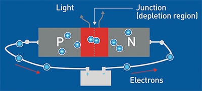
An LED converts electrical energy into light by recombining charge carriers (electrons and holes) at or adjacent to the LED's junction (Figure 1). Unfortunately, even though LEDs are relatively efficient, approximately 65 to 75 percent of the electrical energy consumed still generates heat rather than light, raising the temperature of the chip.

Figure 1: Charge carriers combine at the junction of an LED to generate some light and a lot of heat.
But just how hot can a high-brightness LED get? Let's look at how to determine junction temperature using a simple calculation.
The maximum junction temperature (Tj) attained with a given power input is determined by three factors: ambient temperature, thermal resistance between the LED junction and its surroundings, and the power dissipated by the chip.¹
For ease of calculation, let's assume an ambient temperature (Ta) of 23 degrees Celsius (°C). (Note that a comprehensive design calculation should consider the worst case scenario of the maximum ambient temperature that the LED will experience in normal operation.) Lower ambient temperatures will decrease the junction temperature and prolong the life of the LED. This makes LED lighting a good choice for certain applications, such as chilled food display cabinets.
Thermal resistance (Rth) is defined as the rise in temperature of a component per unit of power dissipated (°C/W). It is the reciprocal of thermal conductivity. Metals typically have low thermal resistance and make effective heat sinks, while air, plastics, and wood are poor heat conductors and make effective insulators.
A simplified model of an LED lighting assembly can be two elements in series with the total thermal resistance being the sum of that of each element. The first element is the LED package from the junction (j) to the solder point (sp) on the supporting substrate (Rth j-sp). The second element is the combination of the thermal resistances between the solder point and the outside of the lighting assembly (i.e., ambient (a)) (Rth sp-a). Figure 2 shows a schematic of this arrangement.

Figure 2: Thermal resistance model for a simple LED lighting assembly. (Courtesy: Cree)
The thermal resistance between the LED junction and ambient (Rth j-a) is the sum of these resistances:
The power dissipated by the LED (Pd) is determined by multiplying the LED's forward voltage (Vf) by its forward current (If).
We can now write a formula for the junction temperature of any given LED:
An example calculation
How hot can the LED junction get? Let's put some typical values into our equation and find out.
First, assume the driver circuitry is positioned away from the LED so its heat output doesn't affect the chip. (This is a best practice recommended by LED manufacturers.)
Second, let's use a Cree XM-L Easy White LED as the basis of light. According to the product data sheet, a typical forward voltage is 5.6 V at a forward current of 350 mA. The thermal resistance from the junction to the solder point (Rth j-sp) is given as 2.5°C/W in the data sheet.
Third, we need to remember that lighting fixtures comprise several LEDs in close proximity to generate sufficient light output. Typically, six to ten devices are combined to form what is effectively a "large chip", albeit with multiple junctions, dissipating several times the power of a single device. For example, we'll consider a lighting unit with six LEDs, and the total power dissipation will be 11.76 W.
Moreover, because the devices that comprise the lighting unit are connected to a single solder point, their thermal resistances act in parallel. Consequently, the overall thermal resistance of the LED group in this example is Rth j-sp/6. The total thermal resistance then becomes:
The value of Rth sp-a depends on many factors, such as the flatness and surface finish of the solder pad where the LEDs are connected to the substrate, the substrate itself, and the characteristics of the assembly's outer shell. For a lighting assembly using standard electronic and industrial materials, and disregarding any thermal management techniques, Rth sp-a is typically within the range of 15 to 25°C/W. For our example, let's take the mid-range value of 20°C/W.
With these values, the calculation for junction temperature becomes:
Cree specifies a maximum junction temperature of 150°C for the XM-L Easy White LED. Consequently, the LEDs will overheat in this configuration and other configurations should be considered.
Reducing junction temperature
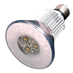
High power LED manufacturers, such as OSRAM, recommend using heat sinks between the solder point and ambient to keep the junction temperature down. Figure 3 shows an LED lighting fixture with an integrated heat sink from the company.

Figure 3: This LED light assembly from OSRAM includes an integrated heat sink. (Courtesy: OSRAM)
By rearranging the formula (1) above, we can calculate the magnitude of the solder point to ambient thermal resistance (Rth sp-a) such that the junction temperature is maintained at the maximum temperature specified by the manufacturer.
Using a heat sink to lower the thermal resistance of the assembly by about 10.5°C/W for a total thermal resistance of the lighting assembly of 10.8°C/W allows the configuration with six LEDs to operate in a safe range. Even the most basic heat sink would be able to cope using this configuration. A more sophisticated device would keep the LEDs even cooler, extending their lifetimes and allowing the unit to operate in higher ambient temperatures.
A subsequent article will take a closer look at the design of heat sinks for LED lighting applications.
Reference:
- 1"Cree XLamp LED Thermal Management," Application Note: CLD-AP05.002, Cree Inc.
免责声明:各个作者和/或论坛参与者在本网站发表的观点、看法和意见不代表 DigiKey 的观点、看法和意见,也不代表 DigiKey 官方政策。


 中国
中国