Battery Cell Balancing for Improved Performance in EVs - Part II: Active Balancing Technologies
投稿人:电子产品
2011-12-07
Techniques that equalize the charge/discharge characteristics of a battery’s individual cells are essential for extending the range and service life of electric vehicles and many portable electronic products. In fact, the passive cell balancing technologies discussed in Part I of this series are already part of the protection and management systems in most of the 5 kWh-20 kWh batteries used by today’s hybrid-electric and plug-in-hybrids (PHEVs). These "smart" passive balancing systems use impedance tracking, coulomb counting, and other state-of-charge monitoring techniques (Figure 1).

Figure 1: Battery management plays a critical role in modern EV propulsion systems. (Courtesy of Maxim Integrated Circuits).
Since even these advanced passive balancing systems allow cells with higher capacity to fully charge by repeatedly bleeding off the energy in weaker cells, they can only unlock a portion of a battery’s "stranded" capacity. As a result, there is a lively debate about whether the next generation of pure EVs can tolerate the lost range and lost charge/discharge cycles if their 25-100 kWh batteries are passively balanced.
At least in theory, the better alternative is an active cell balancing system which re-distributes the charge from stronger cells to prop up the weaker cells within a battery stack. But, while electronics manufacturers are promoting the virtues of their early active cell balancing technologies, many battery and electric vehicle manufacturers have concerns about whether active systems’ added cost and complexity are worth the extended range and operational lifetime they provide.
In this article, we will take a closer look at active cell balancing techniques and where they may play a role in the next generation of electric vehicles and other high-capacity storage applications.
Why active cell balancing?
As discussed in Part I, passive ("top") balancing prevents cells with lower capacities from limiting the charge that cells with larger capacities can accept. This is accomplished (Figure 2) using a bleed resistor to unload over-charged cells so their output voltage falls below the charger’s voltage regulation point, so the remainder of the stack can continue charging. To guard against damage, individual cell conditions must be sampled frequently, with laptop batteries typically monitored at 4-10 samples per second (sps) and EV/HEV batteries from 20-100 sps.

Figure 2: Passive cell balancing can be implemented using general-purpose components (Figure 2a) or an application-specific IC (2b). (Courtesy of Infineon and Analog Devices).
While passive top balancing eliminates the risk of catastrophic cell failure and provides some improvement in run time and service life, it effectively reduces a battery stack’s overall current capacity to that of the weakest cell. Since passive balancing is normally done only when the battery is charging, it cannot fix the imbalances that develop during operation (due to internal impedance and self-discharge) which further diminish capacity.
The alternative is active balancing techniques which transfer a stronger cell’s excess charge to one or more cells which need it. Most active systems use switching MOSFETs similar to those used in passive mechanisms except that they substitute inductors for the bleed resistors which serve as the secondary side of a transformer whose primary sits across the entire battery stack (Figure 3).

Figure 3: Inductively-coupled active cell balancing using an MCU to monitor cell voltage and control the inductively-coupled charge pumps. A filter circuit on the MCU’s A/D input allows measurement of cell voltages from the primary side of the charge pump’s transformer. (Courtesy of Infineon).
Active top balancing (Figure 4) is accomplished by momentarily connecting the cell with the higher voltage to its secondary winding of the balancing circuit, creating an induced voltage on the primary winding. The "donor" cell’s switch is then opened and the switch on an "acceptor" cell is closed, allowing the primary’s energy to be driven back into its secondary winding. This technique allows energy to be transferred between cells during charge, standby, or discharge with efficiencies in the neighborhood of 85 percent.

Figure 4: Top balancing using an active magnetic switching circuit (4a) is performed by energizing one of the transformer’s secondary windings to induce currents in its primary winding (4b). (Courtesy of Infineon).
Active inductive balancing can also used to perform "bottom balancing" which allows stronger cells to share their charge with weaker cells. Bottom balancing can be done at any time but is usually done during the discharge cycle as cells with less capacity approach their maximum discharge limits. In this case, the primary winding is energized with a pulse of the battery stack voltage with the secondary switches on all of the cells open. Once the primary is energized, the connection to the secondary winding for the cell to be charged is closed, allowing the stored energy to be transferred (Figure 5). Bottom balancing unlocks energy that would have otherwise been "stranded" inside a battery.

Figure 5: Bottom balancing using an active magnetic switching circuit (5a) is performed by energizing the transformer’s primary side to induce currents in one of the its secondary windings. (5b). (Courtesy of Infineon).
Most active balancing designs employ variations of the technique shown above, but Texas Instruments has developed an alternative architecture they refer to as PowerPump. Instead of the classical one-to-many architecture described earlier, PowerPump shuttles charges between adjacent cells using a simple charge-coupled switch (Figure 6). Operating at roughly 200 kHz, the circuit can switch Q1 to push current from the top cell to the bottom cell through the body diode of Q2. Likewise, charge can be shuttled from the lower to the upper cell by applying the switching waveform to Q2. Since the losses involved are relatively low, it’s practical for a PowerPump circuit to boost a non-adjacent cell by passing the excess charge across several other cells to where it’s needed in a “bucket brigade” fashion.

Figure 6: Texas Instrument’s PowerPump cell balancing technology uses a simple charge shuttling scheme to transfer energy between adjacent cells.
The TI bq78PL114 master gateway battery controller, for example, is part of a complete Li-Ion control, monitoring, and safety solution designed for large series cell strings. Texas instruments also has recently introduced an automotive-grade active balancing solution based on PowerPump technology which will be discussed in the following section.
Implementation strategies
All battery balancing techniques must work within the framework of the battery pack’s other battery management and protection functions. In most automotive designs, the software for cell balancing algorithms and control functions will be run on an automotive-qualified host MCU, typically located within the battery management system (BMS) itself (Figure 7). The BMS MCU can often use the same electronics used to determine cell voltage, charge/discharge current, and state of charge (SOC) for the battery’s "fuel gauge" and charge management systems to perform similar measurements required for its cell balancing operations. As discussed in Part I of this series, a battery cell’s SOC can be determined using precise voltage measurements or, if greater accuracy is desired, combined with coulomb counting, or some other technique which measures the total current flowing in and out of the cell. In either scenario, the cell voltage measurement requires an A/D converter with 12 to 14-bits of resolution.

Figure 7: A block diagram of a typical battery management system. (Courtesy of Texas Instruments).
At present, most manufacturers do not offer complete integrated solutions for active cell balancing, but they do offer off-the shelf products that handle necessary A/D, multiplexing, level shifting, and communication functions that can reduce their parts count, module size, and BOM cost.
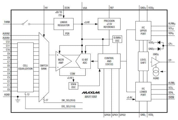
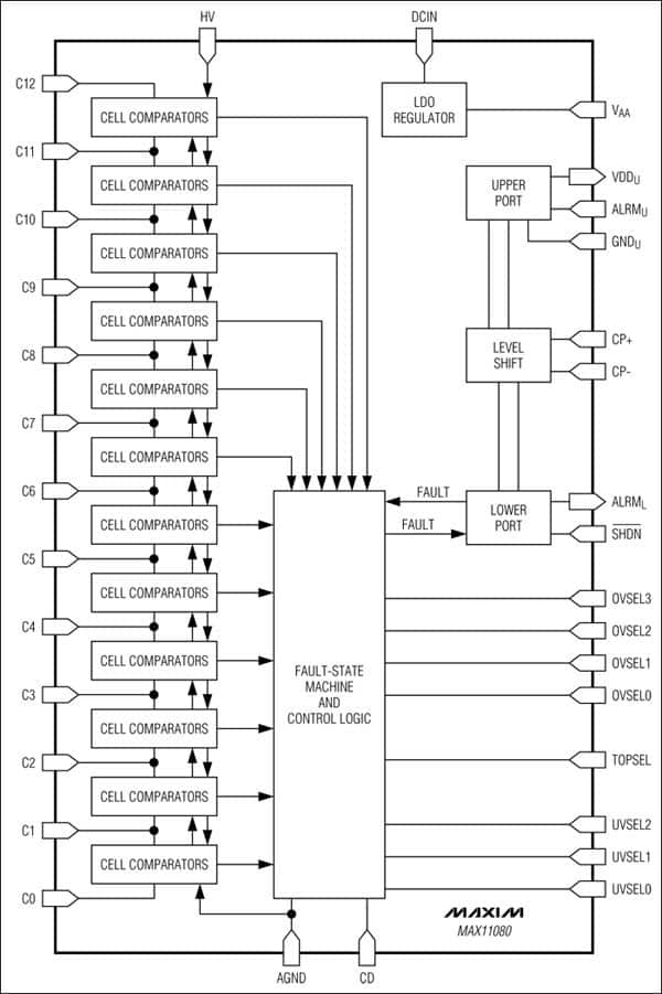
For example, Maxim’s offers a 12-Channel, high-voltage battery monitor developed specifically for Lithium-based automotive storage systems (Fig.8a) combining a 12-bit SAR-type A/D, a high-voltage switch bank input which is controlled by a simple state machine. It is equipped with a high-speed I2C bus for SMBus-laddered serial communication. Rather than rely on the host processor for fault protection, a companion chip, the MAX11080, is used to provide an instantaneous over-voltage or under-voltage fault indication when any of the cells cross the user-selectable threshold for longer than the set program-delay interval (Figure 8b). At present, Maxim’s product line only offers passive balancing solutions but these devices are equally useful as the measurement and protection elements of an active solution.


Figure 8: An integrated battery cell monitoring and protection solution, capable of supporting up to 12 Li-Ion cells.
An active balancing circuit also can be implemented using an addressable driver that allows the host MCU to control a series of power MOSFETS that serve as the switches on the balancing transformer’s primary and secondary legs. MOSFET power devices with fast switching characteristics and low Rdson like Infineon’s OptiMOS series, Microsemi’s CoolMOS devices and Fairchild’s PowerTrench integrated FET+Schottky products have the speed, current capacity, and low switching losses necessary for efficient charge transfer between cells.
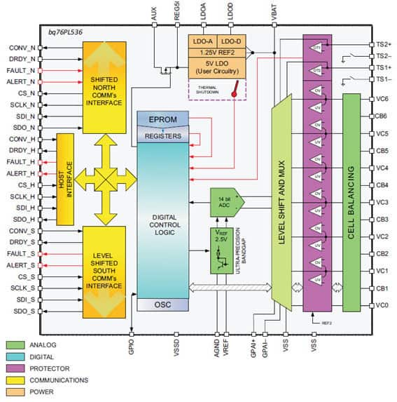
If active cell balancing technology finds acceptance in mainstream applications, it is likely that most IC manufacturers involved with battery management will offer more highly-integrated products that support an active balancing scheme. But, for the moment, the only company to offer an automotive-grade battery management IC with active cell balancing capabilities is Texas Instruments. The bq76PL536-Q1 (Figure 9), based on TI’s PowerPump charge-shuttling technology, provides battery monitoring, electrical/thermal protection and active balancing for up to six cells. Its high-speed (SPI) bus allows the devices to be stacked vertically, providing reliable communications across a high-voltage battery cell stack of up to 192 cells without additional isolation.

Figure 9: A block diagram of Texas Instruments’ bq76PL536-Q1, an automotive-grade battery monitor/protection device with integrated active cell balancing capabilities. (Courtesy of Texas Instruments).
The bq76PL536-Q1 has a second I2C bus that is used to communicate with a host MCU which programs and controls its on-chip monitoring and balancing functions. Fault (secondary) protection for over-voltage, under-voltage, and over-temperature conditions are detected using comparators, so they are independent of the ADC system and host controller to insure rapid, deterministic response. All protection thresholds and detection delay times can be programmed via the I2C host interface and stored in an internal EPROM.
Conclusions
Highly-integrated solutions such as TI’s bq76PL536-Q1 will help narrow the cost differential between active and passive cell balancing systems. But with the low cost of some passive solutions, it is unclear whether the added run time and battery life afforded by active technology will ever outweigh the added cost and complexity it brings to an EV’s BMS. At least part of the answer to this question lies how much improvement manufacturers can deliver in the quality and uniformity of their automotive batteries. If the capacity and impedance variations of today’s cells (typically 2 percent-3 percent) can be further narrowed through advances in manufacturing processes, battery chemistry, and nano-materials, balancing all but the largest EV batteries could be performed with minimal losses using simple, low-cost passive systems. A recent study conducted by Maxim Semiconductor calculated the value of the 10 percent-12 percent extra charge/discharge cycles that active balancing can add to an automotive battery pack. Assuming the battery pack cost $5000, active balancing unlocks around $500 worth of added value, although it is spread out over the vehicle’s 8.5 year service life. If this study is correct, manufacturers may have a difficult time justifying the $70/yr in savings unless the added cost of active balancing is relatively low and it also gives the vehicle a tangible range boost (5 percent-10 percent).
On the other hand, proponents of active balancing technologies say that once highly-integrated solutions arrive, they will cost less to implement than today’s passive systems. These cost savings would mostly be due to eliminating the costly high-power resistors, thermal management components, and the high-current wiring required in the 100+ kWh battery packs that will power the next generation of EVs.
While it’s still too early to determine whether active cell balancing will become the de facto standard for EV/HEV battery management systems, it’s a sure bet that it will be the technology of choice in high-performance vehicles and other applications where run time, energy efficiency and service life are essential.
免责声明:各个作者和/或论坛参与者在本网站发表的观点、看法和意见不代表 DigiKey 的观点、看法和意见,也不代表 DigiKey 官方政策。


 中国
中国