Arduino Embraces 32-bit Microchip MCUs and Other Advanced Processors
投稿人:电子产品
2012-11-14
Originally created as a simple development platform to put inexpensive, easy-to-use embedded systems in the hands of hobbyists, artists, and other non-professionals, the Arduino open-source hardware platform is attracting a rapidly-growing user base. The low-cost modules originally found traction within the hacker community which used them to animate artwork, control “smart clothing” and serve as the brains within low-cost 3D printers. This quickly led to commercial versions of those 3D printers and other Arduino-powered machine tools that may help jump-start a micro-manufacturing revolution. Meanwhile, the open-source technology is being used to develop other commercial products such as controllers for lighting, HVAC and irrigation systems.
It’s no wonder, then, why several leading manufacturers1 have decided to expand their development platforms to take advantage of Arduino’s rich ecosystem of open-source app libraries, reference designs, and easy-to-use dev tools. Although the resources were originally created to support Atmel’s AVR processor architecture, their open-source design made it easy to adapt them to other MCUs. Microchip Technology was one of the first companies to take advantage of this when it collaborated with Diligent to introduce Uno and Mega boards based on its 32-bit MIPS M4K-powered PIC32 MCU. Both NXP and STMicroelectronics quickly followed with form factor-compatible Arduino boards for their 32-bit ARM Cortex MCUs. Meanwhile, more third-party developers are creating families of Arduino boards based on other processors including Atmel’s ARM7-based SAM7X series, Microchip’s dsPIC33F, and Freescale’s 8-bit S08 and 32-bit MCF51 Coldfire MCUs. The broad range of hardware options supported by the Arduino ecosystem opens up exciting new possibilities for developers involved with applications such as image/audio processing or real-time control which can benefit from the extra processing power, memory or advanced features these devices offer.
After having published several articles about the original 8-bit Arduino boards in DigiKey’s TechZones2 (including “Arduino Open Source Platform Unleashes Creativity”) I was itching to take one of these high-powered boards for a test drive. Happily, Microchip offered to loan me its Uno32 board, a pin-compatible version of the much-loved Arduino Uno board powered by their PIC32MX320F128 processor. They also threw in a Max32 board, which duplicates the functionality of the Arduino MEGA board, but with a few helpful enhancements. My ‘care package’ also included a networking shield (something that Diligent calls Basic I/O Shield) that contains a collection of switches, LEDs, a small LCD display and other I/O hardware.
Shortly after the box from Microchip arrived, I headed into the basement and cleared off some bench space in the lab I’d built in the corner of our 1970s-era family room (complete with shag carpet, Lava Lites, and a wet bar) with the idea of seeing how well these boards worked within the Arduino development environment — and what sort of havoc I could wreak with them.
The same but different
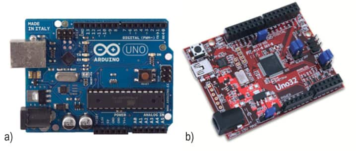
Once on the lab bench, a quick comparison revealed that while the Uno32 board was designed to be functionally compatible with the original Uno board (Figure 1a), it is definitely not your Dad’s Arduino. The most obvious difference is the Microchip PIC32MX320F128 processor, which features an 80 Mhz 32-bit MIPS core, 128 K Flash, 16 K SRAM and 42 I/O lines. In contrast, the 16 MHz 8-bit ATmega MCUs used in the Uno are usually equipped with 4-32 Kbytes of flash, 1-2 Kbytes of SRAM, and 20 I/O pins (14 digital and 6 analog).
To accommodate the PIC32’s larger I/O compliment the ChipKIT engineers added a second row of pins — input/output connectors J5, J6, and J7 (Figure 1b). The board’s pinout is essentially a superset of the original Uno with 2x8 female pin header connectors replacing the single-row connectors J5 and J6 that provide digital I/O signals. The outer row of pins (closer to the board edge) corresponds to the I/O connector pins on an Arduino Uno or Duemilanove board. The inner row of pins provides access to the extra I/O signals provided by the PIC32 microcontroller. Connector J7 is a 2x6 female pin header connector that provides access to the analog input pins on the microcontroller. As with the digital I/O, the outer row of pins corresponds to the original Uno’s six analog pins while the pins of the inner row are used by the additional I/O signals available from the PIC32 microcontroller. The analog pins on J7 can also be used as digital I/O pins.
In keeping with the convention used by the original Arduino designs, the chipKIT/Arduino system uses logical pin numbers to identify digital I/O pins on the connectors. The Uno32 extends the range of logical pin numbers for the I/O pins (from 0-20 to 0-43) but maintains the designated functionality and location of the original pins. To insure clarity, the pins are labeled in the board’s silk screen artwork. Maintaining the original connector locations and naming convention allows the Uno32 to support the I/O used by standard Uno-compatible shields while providing connections that double its overall I/O capacity. For those of you who are counting, both boards use (logical) Pin #13 to drive an on-board LED but the Uno32 uses one of the two extra digital I/O lines that don’t fit on the pin connector (Pin #43) to drive a second on-board LED.

Another welcome addition to the basic Uno design is the Real Time Clock Calendar (RTCC) core that is tucked into the PIC32 microcontroller. Capable of operating when the rest of the MCU is in an idle state, the RTCC circuit can be used to maintain time and date information and provide real-time interrupts for the system. It can also be used to generate “wake-up alarms” for the ARM core, allowing the MCU to spend its idle time in a low-power state. Having an honest-to-goodness hardware RTCC can save gobs of code in any application which involves performing scheduled tasks. To save on BOM costs, the basic kit is not shipped with the 32.768 KHz frequency source used by the RTCC. But a frequency source can be quickly added by soldering a generic 32 MHz watch crystal (such as the Citizen CFS206-32.768KDZF-UB) into the board’s X2 component mounting holes. I’m looking forward to adding the crystal and messing around with the RTCC as I’m thinking of building an Arduino-powered energy manager or garden irrigation controller once I’m more comfortable with programming the boards.
Straightforward programming
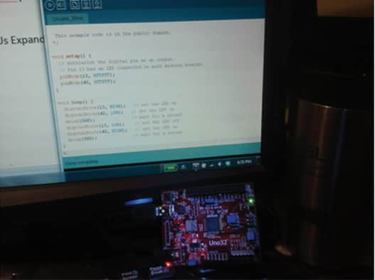
Speaking of programming, it’s been nearly 20 years since I spent any significant time knocking together code for embedded systems (mostly in assembler or raw Hexadecimal) so I was a bit worried that my limited experience with modern programming practices and partly-fossilized 56 year-old brain would prove to be insurmountable barriers to mastering the Arduino development environment. Fortunately, (see Figure 2) the Arduino platform’s straightforward programming language and its open-source development tools are making it surprisingly easy for me to get up to speed. There is a multi-platform version of the Arduino Integrated Development Environment (IDE) that is designed to accept configuration files for both a particular processor and the physical characteristic of the board it’s running on. Diligent, the manufacturer of the Microchip-powered ChipKIT boards has posted the MPIDE and the configuration files for its products at the github hosting site.3

After configuring the IDE, you also have to install drivers in your PC’s operating system that allow the IDE to use one of its USB ports as a COM port which will serve as a boot loader and diagnostic port for the Arduino board. The “official’ Arduino site has a very nice step-by-step tutorial on this procedure for Windows, Mac, and Linux host systems. During the process, I encountered a few minor Microchip-specific issues but they were quickly resolved with a visit to the ChipKIT user forum.5 The forum is fairly active and well-organized, making it easy to locate bug fixes, tech advice, and even some sample code to help you get started with the board’s advanced capabilities.
Despite having explored most of the detours and dead-ends a newbie is likely to stumble down, it only took a few hours to install and configure the IDE on the lab’s computer and do a careful “pre-flight” of the Uno32 board’s jumpers, connectors in preparation for initial power-up. Once the board was connected to the laptop’s USB port for a quick “smoke test,” its power indicator LED lit up and Windows signaled it had detected a new USB device on the COM5 port. So far, so good. With the possibility of a lab bench fire put to rest, I loaded IDE with a simple “blink” program from the demo library and uploaded it to the board.
/*
Double_Blink
Alternately blinks the ChipKIT Uno32's two on-board LEDs with one second interval in each state.
On and off intervals can be adjusted as desired by changing the value of the variable "delay."
Delay values are expressed in 1/1000th of a second.
The example code (Blink) used as the basis for this program is in the public domain.
*/
void setup() {
// initialize the digital pins as an output.
// Pin 13 has an LED connected on most Arduino boards, the Uno32 board has a second LED connected to Pin 43:
pinMode(13, OUTPUT);
pinMode(43, OUTPUT);
}
void loop() {
digitalWrite(13, HIGH); // set the LED on
digitalWrite(43, LOW); // set the LED on
delay(1000); // wait for a second
digitalWrite(13, LOW); // set the LED off
digitalWrite(43, HIGH); // set the LED on
delay(1000); // wait for a second
}
The two LEDs that indicated serial port activity winked frantically for a few seconds and then stopped and the LEDs tied to pins 13 and 43 began to alternate at one-second intervals. I’d finally arrived at the outskirts of Arduino-ville. And the neighborhood looks very friendly indeed.
Next steps
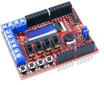
The novelty of blinking LEDs wore off quickly so I started experimenting with some of the other demo code programs and installing the files that will allow the IDE to compile code that controls the networking and I/O shields (Figure 3). The I/O shield contains a handy assortment of hardware and circuits that allow the MCU to interact with the “real world,” which should come in handy for many of the projects I am contemplating building. In addition to a compliment of machine readable push buttons and slide switches, the board contains an analog potentiometer that can be read by one of the board’s analog input channels. There is also an I²C temperature sensor and a 256 Kbit EEPROM that can be accessed by the processor’s I²C bus and four open drain FET drivers that can be used to drive high-powered devices without placing a strain on the board’s own supply.

Once the IDE is modified for the shield boards, I want to develop a benchmark program that will provide some sort of useful metric about how various processors perform within the Arduino environment. Having even a simple benchmark score that indicates how quickly a particular processor handles I/O and memory operations and the tasks related to audio or video processing and other specific functions will be very helpful in finding the right MCU for an application.
I am in the process of trying to define the types of tasks I want to include and what sort of scoring system to use for the benchmark so I’ll also be devoting a little time to picking out the first application I want to develop for my Arduino boards. At present, I am torn between an irrigation controller for the four raised bed gardens in my backyard or a motion controller to animate a zombie mannequin for the haunted Halloween house a friend of mine built in his garage.
References:
- A list of Arduino boards with alternative (non-Atmel) MCUs:
http://en.wikipedia.org/wiki/List_of_Arduino_compatibles#Non-ATmega_boards - Additional TechZone articles on Arduino technology:
- Downloads of the Arduino MPIDE that supports the Uno32, Max32, and other ChipKIT32 product family members are available for Windows, Mac OC and Linux at the github hosting site:
https://github.com/chipKIT32 - ChipKIT user forum
http://www.chipkit.org/forum/
免责声明:各个作者和/或论坛参与者在本网站发表的观点、看法和意见不代表 DigiKey 的观点、看法和意见,也不代表 DigiKey 官方政策。


