Android as a Sensor Platform in Phones, Tablets, and E-Readers
投稿人:电子产品
2012-05-17
Android devices are now part of the array of gadgets offering sensor-based capabilities that let developers do everything from determining how often someone drops his or her phone, to allowing users to control applications and games by tilting, shaking, or pointing their phones.
The open-source Android platform is ideal for creating innovative apps using hardware sensors. It is not, however, optimized for real-time sensor data acquisition and requires intelligent algorithms to process and then provide usable sensor information.
Gaming is one of the more popular sensor applications for Android handsets. Gaming applications use gyroscopes, accelerometers, and compasses to enable such rich user experiences as “flying” through tunnels, and games where the players experience or simulate motion in any direction. As an example, consider Nintendo’s use of motion sensing in its Wii system games, which allow the user to interact with and manipulate items on screen via gesture recognition and pointing, through the use of accelerometer and optical sensor technology.
The Android platform itself provides a rich opportunity for sensors to monitor and interact with the handset environment. Sensors that can and are currently being used include accelerometers, gyroscopes, compasses, as well as pressure, temperature, and image sensors. For the purpose of this article, only the first three will be discussed, both as independent devices and, via sensor fusion, as a system, so that:
- Gyroscopes provide orientation and good dynamic response
- Accelerometers provide correction due to gravity
- Compasses provide correction due to magnetic north
Here’s the magic behind sensors used in the Android OS: you can access the underlying hardware in devices using the OS as hardware capabilities are brought to the surface for easy developer use. Android is an open-source software stack for mobile devices. It is open source because Google wanted to make sure that there was no central point of failure, and that no one industry player could restrict or control the innovations of any other. With an open-source platform, and by downloading the Android SDK, you have unprecedented access to these sensor-related features:
android.hardware.SensorManager - This is a class that gives access to the sensors available within the Android platform.
android.hardware.SensorListener – An interface that is implemented by a class to receive updates to sensor values as they change in real time so that it can monitor one or more sensors in the hardware.
android.hardware.SensorManager Contains constants that represent different aspects of Android's sensor system, including:
- Sensor type
- Sampling rate
- Accuracy
Native libraries exposed by the platform let applications handle the same types of input events as those available through the framework. Applications can receive events from all supported sensor types and can enable/disable specific sensors and manage event delivery rate and queuing. Let’s now examine the types of sensors that can be applied to Android platforms.
Gyroscopes
Gyroscopes are angular velocity sensors that measure their own rotation using the Coriolis Effect. This effect takes place when a mass is moving and a frame of reference is rotating. A gyroscope moves a mass very quickly so that it oscillates and creates a Coriolis Effect is a result of this oscillation. When the mass oscillates at approximately 30 kHz, capacitive sensors can pick up this signal. In handheld instruments such as Android smartphones, a three-axis gyroscope vibrates and senses rotation. Physically, silicon is placed under the sensor with the necessary logic and a larger chip often is placed under that in the stack to perform signal conditioning and sensor fusion, taking input from other sensors in the system.
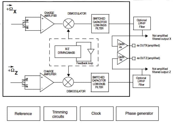
The STMicroelectronics LPY450AL MEMS motion sensor (Figure 1) is a dual-axis pitch-and-yaw ±500 dps analog gyroscope used in pointing devices and game controllers. It is a low-power, dual-axis micromachined gyroscope capable of measuring angular rate along pitch and yaw axes, providing temperature stability and high resolution over an extended operating temperature range (–40° to 85°C). The LPY450AL has a full scale of ±500 dps and is capable of detecting rates with a -3 dB bandwidth up to 140 Hz.

The device includes a sensing element composed of a single driving mass, kept in continuous oscillation and capable of reacting, based on the Coriolis principle, when an angular rate is applied. A CMOS IC provides the measured angular rate to the external world through an analog output voltage, allowing high levels of integration and production trimming to better match sensing element characteristics. The LPY450AL is available in a plastic land grid array (LGA) package.
Accelerometers
An accelerometer is a sensor that measures acceleration, the rate of change in velocity across time. Velocity is described using a vector, which — as you will recall from Basic Physics — unlike a scalar has a magnitude and (this is the key) direction. In a phone, a three-axis accelerometer provides orientation, indicating whether the phone is facing up or down, whether the screen is facing the user, or is upside down and all combinations in between. In a phone, the accelerometer is designed to pick up all movement, including tilt, pitch, and roll.
To apply shaking to a phone’s repertoire of controls, an algorithm can be developed examining rapid change in the direction of gravity relative to the phone’s axis. Here, rapid change in the Tilt X, Y, and Z values is detected and a threshold value can be set to determine when rapid-enough change is occurring and, at the same time, filters out slow-moving change such as simply answering or picking up the phone rather than shaking it.
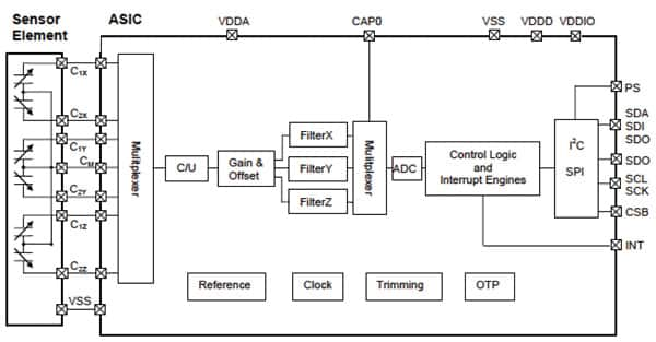
An example of an acceleration sensor is the BMA220 by Bosch (Figure 2), a triaxial ±2 to ±16 g acceleration sensor with on-chip motion-triggered interrupt controller. The sensor is a three-axis accelerometer with an ultra-small package size (2 x 2 x 0.98 mm). The digital interface SPI (four-wire, three-wire) I2C, interrupt pin, and has an I/O supply voltage range of 1.6 to 3.6 V. It features programmable functionality.


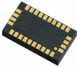
Another example is the LSM320DL (Figure 3) linear sensor module by STMicroelectronics. It is a system-in-a-package featuring a 3D digital accelerometer and a 2D digital gyroscope. The various sensing elements are manufactured using specialized micromachining processes, while the IC interfaces are realized using a CMOS technology that allows you to design a dedicated circuit which is trimmed to better match the sensing element characteristics. LSM320DL has a dynamic user selectable full-scale acceleration range of ±2 g, ±4 g, ±8, and ±16 g, and angular rate of ±250, ±500, and ±2,000 degrees/s.
The accelerometer and gyroscope sensors can be either activated or put in low-power or power-down mode separately for application-optimized power saving. The LSM320DL is available in a plastic land grid array (LGA) package. The part targets such applications as GPS navigation, impact recognition and logging, gaming and virtual reality input devices, motion activated functions, vibration monitoring and compensation, free-fall detection, and 6D orientation detection.
The compass
Compasses, used in conjunction with an accelerometer, provide magnetic north orientation. Magnetic-field sensors work in a noisy environment, picking up every possible magnetic field, which includes interference from Bluetooth chips, speakers, microphones, virtually anything on a circuit board that is magnetized. Compasses work when current on a wire is deflected by the Hall Effect, that being when a magnetic field is present. They can be, and are, created completely out of silicon electronics.
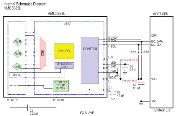
An example of a three-axis digital compass IC is Honeywell’s HMC5883L (Figure 4) surface-mount, multichip module designed for low field magnetic sensing with a digital interface. The HMCa5883L includes a high-resolution HMC 118X series magnetoresistive sensor plus an ASIC with amplification, automatic degaussing strap drivers, offset cancellation, and a 12-bit ADC that enables 1 to 2 in. compass heading accuracy. The I2C serial bus allows for easy interface. Applications include mobile phones, netbooks, consumer electronics, auto navigation systems and personal navigation devices.

The HMC5883L uses Honeywell’s Anisotropic Magnetoresistive (AMR) technology providing precision in-axis sensitivity and linearity. The solid-state construction with very low cross-axis sensitivity is designed to measure both the direction and magnitude of Earth’s magnetic fields.
Sensor Fusion
In a handheld phone sensor, data from the above-mentioned components is put together, creating what is known as sensor fusion. For example, taking a gyroscope and finding orientation, and then using an accelerometer to keep the orientation correct with respect to gravity – while removing drift – enables you to create an effective application, while using the data independently and alone from each of the sensors would not give you a desirable result.
Similarly, a compass requires tilt compensation. It is impossible to know a heading unless the horizontal plane is understood relative to how a device is held. Tilt compensation is performed with accelerometers, but they do not measure gravity. Both accelerometers and gyroscopes are used to tilt compensate the compass.
Development is continuing
The use of gyroscopes, accelerometers, and compasses in mobile application development is certainly going to increase. When these sensors are combined with mobile GPS, light sensors and other inputs, new and exciting interactions with applications become possible. There already are a number of fairly sophisticated actions that can be performed on platforms such as Android (or an iOS and Windows Mobile devices, for that matter) through the use of a variety of sensors combined with sensor fusion. We have presented examples of sample parts and applications, and more information on the products mentioned can be found by using the links provided to access product pages on the DigiKey website.
免责声明:各个作者和/或论坛参与者在本网站发表的观点、看法和意见不代表 DigiKey 的观点、看法和意见,也不代表 DigiKey 官方政策。


 中国
中国