An Easier Approach to High-Performance Current Loop Control Design
投稿人:DigiKey 北美编辑
2017-09-27
Current loop control has long played an essential role in process control systems and automated manufacturing facilities. To meet demand for higher performance servo systems, manufacturers have required faster current loop control solutions implemented in complex designs based on high-speed FPGAs and costly signal chains.
However, this article will show, using real-world solutions from Texas Instruments, that recent advances in microcontroller hardware and software capabilities have made it possible to lower the cost of implementation, without sacrificing performance.
Control loop operation
In many control systems, designers rely on proportional-integral (PI) control loops to manage current or other performance characteristics. In principle, these controllers are simple. They use the error between desired and measured performance to generate a correction signal based on the output of two error processing paths (Figure 1). The proportional (P) path applies gain to the error; the integral (I) path integrates the error and amplifies the result.

Figure 1: A proportional-integral (PI) control loop generates a correction signal that combines the integrated measured signal error output with a path that applies a simple proportional gain to the error signal. (Image source: Texas Instruments)
Unlike simpler control applications, servo motor designs depend on three interdependent performance characteristics: position, speed, and current. To change position of the motor rotor, its velocity needs to change. In turn, to change its velocity, the current applied to the motor windings through pulse-width modulation (PWM) needs to change. Servo motor control developers reflect this loop interdependence in a cascade control structure as shown in Figure 2.

Figure 2: Cascade servo control systems use nested feedback loops to respond quickly to deviations in performance rather than waiting for the effects to propagate through the entire control structure. (Image source: NCTU)
This nested approach inherently aids stability by correcting underlying errors before they can propagate. For example, the innermost current loop can independently modify torque to respond to a change in load well before the load change significantly impacts velocity and position.
At the same time, this nested approach means that outer loops can only perform as well as their underlying inner loops. In servo systems, efforts to enhance position and speed performance will inevitably fall short if the inner loop lacks the bandwidth to support outer loop performance expectations. Ultimately, the performance of the inner current loop effectively defines the limits of performance of the overall servo system.
Current loop control is well understood and conceptually straightforward. A current controller modifies a PWM output that drives the inverter, which in turn supplies power to the windings of a motor (or transformer in a power supply design). Using a fast analog-to-digital converter (ADC) to measure motor current, the controller can determine the correction signal needed to modify the PWM output to achieve the desired motor performance.
At the heart of this conceptually simple process, however, the field oriented control (FOC) algorithms used in digital control systems can present a significant computational burden. FOC algorithms manipulate vector representations of currents, using Park and Clarke transforms to arrive at an optimal solution (Figure 3).
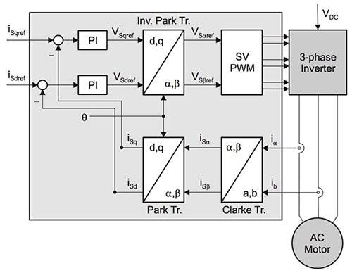
Figure 3: To adjust a PWM output based on measured motor performance, motor control loops use complex vector space representations including Park and Clarke transforms that present significant processing requirements. (Image source: Texas Instruments)
Implemented in software libraries, high-performance MCUs can generate current loops fast enough to meet requirements for conventional servo systems. In these systems, PI controllers typically limit current loop bandwidth to about 10% of the PWM carrier frequency, which typically operates at around 10 kHz.
Higher bandwidth leads to complexity and power management issues
In an effort to improve inner loop bandwidth, designers have boosted PWM carrier frequency to 30 kHz and above. At these higher frequencies, however, conventional current loop designs begin to lag, unable to complete control algorithms rapidly enough. As a result, developers looking to boost inner loop bandwidth have turned to specialized FPGA-based subsystems designed to perform calculation of control algorithms at higher carrier frequencies (Figure 4).

Figure 4: While increasing PWM carrier frequency boosted inner loop performance, it required engineers to build more complex current loop control designs using high-speed FPGAs and ADCs. (Image source: Texas Instruments)
Although the use of these specialized subsystems boosts performance, it also significantly boosts cost and complexity of current loop implementations. Designers need to add components including high-speed, high-resolution ADCs and analog comparators that are typically not integrated into the FPGAs themselves. At both the motor and MCU interfaces with the FPGA, engineers need to ensure maximum throughput, minimizing any delays that can stall performance in this critical processing loop. Besides dealing with additional hardware requirements, designers of these systems need to address additional requirements for FPGA code programming and debug during development, and then eventual storage of production code in the host MCU.
While the use of an FPGA adds its own set of additional hardware and software requirements, the use of higher PWM frequencies impacts the design on a fundamental level. Operation at higher frequencies can mean additional inverter switching losses and the need for higher power drivers. This in turn translates into requirements for larger, higher output power supplies. The increased power levels lead to the need for more robust thermal management.
Beyond increasing design complexity, size and cost, the additional requirements associated with FPGA-based current loop designs may impact project schedules and final delivery. In contrast, specialized MCUs and software from Texas Instruments eliminate the complexity of FPGA-based current loop control.
Optimized MCU-based solutions simplify high-performance loop designs
By taking advantage of specialized features on Texas Instruments TMS320F28379S single-core and TMS320F28379D dual-core C2000 Delfino MCUs, the TI Fast Current Loop (FCL) software library enables servo designers to achieve high-bandwidth performance of the inner control loop without increasing PWM carrier frequency. Using this approach, developers can build highly responsive servo applications using familiar MCU-based design and software development methods.
TI’s approach completes FOC processing and performs PWM updates in under 500 nanoseconds (ns), allowing sub-cycle PWM updates rather than waiting for an entire control loop cycle to pass. This approach lets developers achieve over 3 kHz control loop bandwidth at 10 KHz PWM carrier frequency, tripling control loop bandwidth, without tripling PWM carrier frequency as required with FPGA-based methods.
The key to the enhanced performance of this simpler design approach lies in the specialized C2000 MCU structures that combine with FCL software to provide functional and performance equivalents of conventional FPGA-based control loops (Figure 5). Based on TI’s 32-bit C28x floating-point CPU, these specialized MCUs integrate a full complement of analog and digital peripherals with specialized functional blocks.
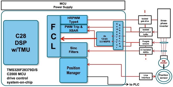
Figure 5: Integrated peripherals and specialized blocks in the TI TMS320F28379S and TMS320F28379D C2000 Delfino MCUs provide the functional and performance equivalents of control loop elements, previously built with FPGAs, to achieve fast current loop performance. (Image source: Texas Instruments)
Rather than just a collection of on-chip features, TI designed these peripherals and blocks with particularly tight integration geared toward high-speed control loop operations. For example, to capture data used in control loop calculations, the MCU integrates a flexible analog signal chain comprising a comparator subsystem (CMPSS) and four high-speed ADCs. Each CMPSS includes a dedicated analog signal path (Figure 6) with outputs connected to integrated crossbar switches, connected to a GPIO multiplexer, ADCs, and PWM subsystem. Similarly, engineers can use crossbars to direct outputs from the ADCs to PWMs and other blocks.
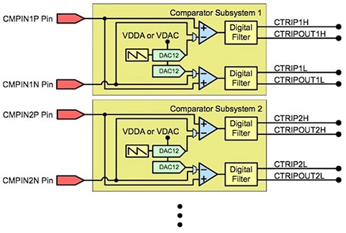
Figure 6: TI achieves FPGA-like control loop performance by building on tightly integrated features such as the comparator subsystem used at the input of its MCU-based control loop solution. (Image source: Texas Instruments)
An on-chip Sigma-Delta Filter Module (SDFM) includes four independent comparators and four independent filters, which support the sinc filter functionality used in the control loop shown in Figure 5. On the output of the control loop, the MCU combines its enhanced PWM subsystem with a high-resolution pulse width modulator (HRPWM) featuring step size resolution of 150 picoseconds (ps) (typical). Within the PWM block, a trip submodule responds to a broad array of fault or forced event conditions to mitigate issues such as short circuits or overcurrent conditions.
Along with these advanced I/O subsystems, the MCUs provide specialized blocks needed to round out support for high-speed control loop designs. Among these blocks, the integrated Configurable Logic Block (CLB) provides resources needed to implement logic functions that would otherwise require additional external devices. For developers, TI provides a series of software resources that configure the CLB to support specific types of functionality.
For high-speed current loops, in particular, TI provides software that uses the CLB to provide the position manager functionality shown in Figure 5. In this case, the position manager supports industry standard bidirectional encoder interfaces such as EnDat and BiSS.
Designed specifically for transmitting position and control data, these bidirectional encoder interfaces present significant performance requirements. BiSS solutions are typically based on FPGAs or ASICs, particularly for implementation of continuous-mode BiSS, or BiSS-C. Instead, TI’s BiSS-C position manager implements the encoder interface using a combination of software running on the MCU and MCU hardware resources including the SPI interface, crossbar, and CLB (Figure 7).
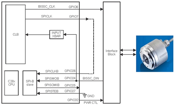
Figure 7: TI uses the MCU configurable logic block (CLB) and other MCU features to implement complex logic such as the continuous mode bidirectional serial synchronous (BiSS-C) encoder interface. (Image source: Texas Instruments)
In providing a high-speed current loop solution, TI combines these resources with its FCL library, which handles the FOC calculations noted earlier. Here, the library takes further advantage of specialized MCU hardware, including an integrated trigonometric math unit (TMU) and control law accelerator (CLA), which off load math intensive processing from the processor core. For example, control loop code can use the CLA to independently handle encoder feedback and use the TMU to perform Park and Clarke transforms at a rate nearly an order of magnitude faster than processor-based calculations.
Hiding complexity
Perhaps most importantly, the FCL library hides the complexity of all the detailed operations required to implement servo loop control, allowing developers to focus on their unique requirements. The FCL application programming interface (API) comprises only a few functions shown in Table 1.
|
Table 1: The Texas Instruments Fast Control Library (FCL) hides the complexity of FOC-based current loop control behind a short, simple API. (Table source: Texas Instruments)
Along with C interface declarations for these functions, the FCL header file includes a few additional package references and a key C structure that holds the few required parameters associated with the current loop (Listing 1).
Copy
// ==============================================================
typedef struct currentLoopPars {
       float32  CARRIER_MID,    // Mid point value of carrier count
                      ADC_SCALE,      // ADC conversion scale to pu
                cmidsqrt3;      // internal variable

       float32 tSamp,           // sampling time
                     Rd,              // Motor resistance in D axis
                     Rq,              // Motor resistance in Q axis
                     Ld,              // Motor inductance in D axis
                     Lq,              // Motor inductance in Q axis
                     Vbase,           // Base voltage for the controller
                     Ibase,           // Base current for the controller
                     wccD,            // D axis current controller bandwidth
                     wccQ,            // Q axis current controller bandwidth
                     Vdcbus,          // DC bus voltage
                     BemfK,           // Motor Bemf constant
                     Wbase;           // Controller base frequency (Motor) in rad/sec
} FastCurrentLoopPars_t;
Listing 1: Texas Instruments’ integrated control loop solution means that developers need only a few software structures such as this one for control loop parameters provided in the TI controlSUITE software package. (Code source: Texas Instruments)
Although the FCL library hides the complexity of designing FOC-based current loops, the complexity of servo control operation is inescapable. To help developers evaluate performance and gain experience with servo control operation, Texas Instruments provides the TMDXIDDK379D DesignDrive development kit, which offers a complete implementation of a servo control design based on the TI FCL library. Along with the hardware board, TI provides a complete set of schematics and manufacturing data that developers can extend to develop their custom servo applications.
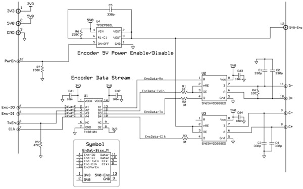
Because the critical control loop mechanisms are built into the underlying MCU and FCL library, developers require relatively few additional components to implement a complete servo design. As detailed in the schematics, designs can implement the hardware side of an EnDat or BiSS encoder interface using a few passive components and three TI devices: the SN65HVD3088ED RS485 transceiver; the TXB0104DR level translator; and the TPS27082L high-side load switch (Figure 8).
Figure 8: Schematics included in the Texas Instruments controlSUITE package demonstrate simple hardware interfaces such as this minimal EnDat-BiSS interface needed to complement the full encoder functionality implemented on-chip using the MCU CLB. (Image source: Texas Instruments)
As with hardware design, software design is conceptually simpler with the TI fast control loop solution. Because the MCU’s combination of dedicated hardware and specialized firmware do all the work, software development is largely a process of setting up the MCU and configuring the platform. For example, the TI software package provides a simple main() routine that comprises hundreds of lines of code strictly concerned with initializing MCU and FCL features and configuring its setup. The actual main routine is just an empty wait loop (Listing 2).
Copy
//*****************************************************************************
void main(void)
{

       //  Initialize System Control:
       // PLL, WatchDog, enable Peripheral Clocks
       // This example function is found in the F28M3Xx_SysCtrl.c file.
       InitSysCtrl();

       // Only used if running from FLASH
       // Note that the variable FLASH is defined by the compiler

#ifdef _FLASH
// Call Flash Initialization to setup flash waitstates
// This function must reside in RAM
       InitFlash();  // Call the flash wrapper init function
#endif //(FLASH)
     .
     .
     .
       // Enable Interrupt Generation from the PWM module
       EPwm1Regs.ETSEL.bit.INTEN=1;
       // This needs to be 1 for the INTFRC to work
       EPwm1Regs.ETPS.bit.INTPRD=ET_1ST;
       EALLOW;

       PieVectTable.ADCC1_INT = &ResolverISR;
       //PieVectTable.EPWM11_INT = &MotorControlISR;
//     PieVectTable.ADCA1_INT = &MotorControlISR;
       PieVectTable.EPWM1_INT = &MotorControlISR;

//     PieVectTable.TIMER1_INT = &TimerISR;


//     PieCtrlRegs.PIEIER1.bit.INTx1  = 1;  // Enable ADCA1INT in PIE group 1
//     PieCtrlRegs.PIEIER3.bit.INTx11 = 1;  // Enable PWM11INT in PIE group 3
       PieCtrlRegs.PIEIER3.bit.INTx1 = 1; //// Enable PWM1INT in PIE group 3

#if POSITION_ENCODER == RESOLVER_POS_ENCODER
       PieCtrlRegs.PIEIER1.bit.INTx3  = 1;  // Enable ADCC1INT in PIE group 1
#endif

       IER |= M_INT3; // Enable group 3 interrupts - EPWM1, 11 are here
//     IER |= M_INT1; // Enable group 1 interrupts - ADCA, B are here
       EINT;          // Enable Global interrupt INTM
       ERTM;          // Enable Global realtime interrupt DBGM
       EDIS;


// ***************************************************************************
//  Initializations COMPLETE
//  - IDLE loop. Just loop forever
// ***************************************************************************
       for(;;)  //infinite loop
       {
              // State machine entry & exit point
              //===========================================================
              (*Alpha_State_Ptr)();      // jump to an Alpha state (A0,B0,...)
              //===========================================================
       }
} //END MAIN CODE
Listing 2: This snippet from software samples in the Texas Instruments controlSUITE demonstrates how setting up fast control loop operation is largely a process of initializing the MCU and fast control loop library; the main routine itself is a simple wait loop. (Code source: Texas Instruments)
Once the MCU is configured at startup, most of the work required to implement a control loop with TI’s approach lies in providing an appropriate interrupt service routine (ISR) for handling motor control tasks. TI demonstrates such an ISR with its MotorControlISR function provided in the fast-control loop sample software module. Enabled during setup (for example, PieVectTable.ADCC1_INT = &ResolverISR in Listing 2), the MotorControlISR function illustrates how software engineers can use the FCL API to perform measurements and generate output (Listing 3).
Copy
// =============================== FCL_LEVEL 3 ======================================
//     Level 3 verifies the dq-axis current regulation performed by PID and speed
//     measurement modules
//  lsw=0: lock the rotor of the motor
//  lsw=1: close the current loop
//  NOTE:-
//         1. Iq loop is closed using actual QEP angle.
//         Therefore, motor speed races to high speed with lighter load. It is better
//            to ensure the motor is loaded during this test. Otherwise, the motor will
//            run at higher speeds where it can saturate. It may be typically around the
//            rated speed of the motor or higher.
//      2. clarke1.As and clarke1.Bs are not brought out from the FCL library
//         as of library release version 0x02
// ==============================================================================

//TODO INCRBUILD 3
#if (BUILDLEVEL==FCL_LEVEL3)


#if  (FCL_CNTLR ==  PI_CNTLR)
    FCL_PI_Ctrl();
#endif

#if (FCL_CNTLR ==  CMPLX_CNTLR)
    FCL_Complex_Ctrl();
#endif

// ------------------------------------------------------------------------------
//    fcl_cycle_count calculations for debug
//    customer can remove the below code in final implementation
// ------------------------------------------------------------------------------
    get_FCL_time();

// ------------------------------------------------------------------------------
//  Measure DC Bus voltage using SDFM Filter3
// ------------------------------------------------------------------------------
    FCL_Pars.Vdcbus = (temp=SDFM1_READ_FILTER3_DATA_16BIT)*SD_VOLTAGE_SENSE_SCALE;
    if (FCL_Pars.Vdcbus < 1.0)
        FCL_Pars.Vdcbus = 1.0;

// ------------------------------------------------------------------------------
// Fast current loop controller wrapper
// ------------------------------------------------------------------------------
       #if  (FCL_CNTLR ==  PI_CNTLR)
              FCL_PI_CtrlWrap();
       #endif

       #if (FCL_CNTLR ==  CMPLX_CNTLR)
        FCL_Complex_CtrlWrap();
       #endif

// ------------------------------------------------------------------------------
// Alignment Routine: this routine aligns the motor to zero electrical angle
// and in case of QEP also finds the index location and initializes the angle
// w.r.t. the index location
// ------------------------------------------------------------------------------
       if(!RunMotor)
       {
              lsw = 0;
              pi_id.Ref = IdRef = 0;
              FCL_ControllerReset();
       }
    else if (lsw == 0)
    {
          // alignment current
          IdRef = IdRef_start;  //IQ(0.1);

          // set up an alignment and hold time for shaft to settle down
          if (pi_id.Ref >= IdRef)
          {
                if (++cntr >= alignCnt)
                {
                           cntr  = 0;
//                         IdRef = IdRef_run;
#if POSITION_ENCODER==QEP_POS_ENCODER
                           lsw = 1;      // for QEP, spin the motor to find the index pulse
#else
                           lsw = 2;      // for absolute encoders no need for lsw=1
#endif
                }
          }
    } // end else if (lsw=0)
    else if (lsw == 2)
        IdRef = IdRef_run;

// ------------------------------------------------------------------------------
//  Connect inputs of the RMP module and call the ramp control macro
// ------------------------------------------------------------------------------
    if(lsw==0) rc1.TargetValue = rc1.SetpointValue = 0;
    else rc1.TargetValue = SpeedRef;
    RC_MACRO(rc1)

// ------------------------------------------------------------------------------
//  Connect inputs of the RAMP GEN module and call the ramp generator macro
// ------------------------------------------------------------------------------
    rg1.Freq = rc1.SetpointValue;
    RG_MACRO(rg1)

    posEncElecTheta[POSITION_ENCODER] = qep1.ElecTheta;
    speed1.ElecTheta = posEncElecTheta[POSITION_ENCODER];
    SPEED_FR_MACRO(speed1)

//------------------------------------------------------------------------------
// Variable display on DACs B and C
//------------------------------------------------------------------------------
    DacbRegs.DACVALS.bit.DACVALS = DAC_MACRO_PU(pi_iq.Ref);  //rg1.Out*4096;
    DaccRegs.DACVALS.bit.DACVALS = DAC_MACRO_PU(pi_iq.Fbk);  //posEncElecTheta[POSITION_ENCODER]*4096;

// ------------------------------------------------------------------------------
//  setup iqref for FCL
// ------------------------------------------------------------------------------
    pi_iq.Ref = (lsw==0) ? 0 : IqRef;

// ------------------------------------------------------------------------------
//  setup idref for FCL
// ------------------------------------------------------------------------------
    pi_id.Ref = ramper(IdRef, pi_id.Ref, _IQ(0.00001));

// ------------------------------------------------------------------------------
//  Connect inputs of the DATALOG module
// ------------------------------------------------------------------------------
    DlogCh1 = posEncElecTheta[POSITION_ENCODER];
    DlogCh2 = rg1.Out;
    DlogCh3 = pi_iq.Ref;
    DlogCh4 = pi_iq.Fbk;

#endif // (BUILDLEVEL==FCL_LEVEL3)
Listing 3: The Texas Instruments controlSUITE sample software shows how developers can largely relegate control loop implementation code to an interrupt service routine, which in turn needs only make a few API calls to the TI fast control loop (FCL) library. (Code source: Texas Instruments)
Although the demo kit and software help simplify development, servo control operations can be daunting to less experienced engineers. To help designers better understand servo control, the TI development suite lets them explore its operation through a series of incremental build levels. Here, developers select the build level simply by setting BUILDLEVEL (see, for example, Listing 3). After demonstrating basic PWM signal output (Level 1) and open-loop operation (Level 2), developers use the next three build levels to closely examine the operation of each nested loop of a full servo control design (Figure 9).
Figure 9: Using the TMDXIDDK379D DesignDrive development kit and TI controlSUITE software, developers can explore servo control designs in a series of stages, first evaluating the innermost current control loop (green), then adding the velocity loop (blue), and finally adding the position loop (orange) in a complete servo design. (Image source: Texas Instruments)
By setting BUILDLEVEL=FCL_LEVEL3, for example, developers can explore the operation of the inner loop itself. Within this level, developers can even test the effect of using different underlying mechanisms or parameters. For example, by setting FCL_CNTLR in the Level 3 ISR (see Listing 3), developers can choose to operate the loop using the PI controller (FCL_CNTLR=PI_CNTLR) or complex controller (FCL_CNTLR=CMPLX_CNTLR). As shown in Listing 3, conditional compilation based on the FCL_CNTLR setting simply results in a call to the respective FCL API routine (see Table 1). Using this approach, developers can gradually immerse themselves by stages into the operations of a complete servo control design, eventually building on the TI development kit to create their own high-speed servo applications.
Conclusion
In servo loops, the performance of the inner current control loop effectively defines the limitations of the servo control application as a whole. In the past, developers looking to enhance the inner loop have been forced to boost PWM carrier frequency, and support the higher frequency with subsystems built with FPGAs and high-speed ADCs.
Rather than face the cost and possible delays associated with this approach, developers can take advantage of a simpler solution from TI that combines a specialized MCU and software library. Using this approach, developers can create servo control applications that achieve inner-loop performance once possible only with specialized FPGA-based designs at a fraction of the time and cost.

免责声明:各个作者和/或论坛参与者在本网站发表的观点、看法和意见不代表 DigiKey 的观点、看法和意见,也不代表 DigiKey 官方政策。


