Adding Heart-Rate Monitoring Functionality to Fitness Gear
投稿人:DigiKey 北美编辑
2016-11-16
Consumer driven on-demand fitness metrics create opportunities for applications using a heart-rate monitor (HRM) embedded not only in smart watches and fitness wearables, but also in exercise equipment. Among HRM approaches, pulse oximetry offers the greatest consumer convenience. However, challenging requirements in electronic, mechanical, and software design of pulse oximetry functionality can add significant complexity and delay to the implementation of the end product itself.
An integrated biosensor such as the Maxim Integrated MAX30102 offers a simpler approach for implementing HRM in dedicated wearables or fitness equipment.
HRM information demand
Heart rate is one of the most familiar and accessible gauges of exercise intensity. Health organizations state exercise intensity targets in terms of maximum heart rate, which is generally accepted as the value 220 minus the individual's age. The American Heart Association recommends that most individuals should exercise at an intensity around 50% of maximum when beginning an exercise program, and no more than 85% of maximum later.
Fitness buffs and athletes use finer gradations of heart rate intensity levels to achieve specific training conditions (see Table 1). At 72-78% of maximum heart rate, training crosses the threshold from aerobic to anaerobic training. Exercise below this level offers central cardiac system benefits such as improved cardiac output. Training above this threshold offers benefits to the periphery such as improved capillarization.
At 86-92%, training reaches the onset of blood lactate accumulation (OBLA), where lactate builds up to significant levels with noticeable degradation in performance. Training at OBLA levels increases the individual's ability to clear lactate and enhances muscle performance in well-trained athletes.
| Zone | % Maximal Heart Rate | Training Type |
|---|---|---|
| 5 | 93 - 100% | Maximal training |
| 4 | 86 - 92% | OBLA training |
| 3 | 79 - 85% | Steady-state training |
| 2 | 72 - 78% | Lactate threshold training |
| 1 | 65 - 71% | Moderate |
Table 1: Athletes use heart-rate measurements to target specific types of training. (Source: American College of Sports Medicine)
Along with heart rate, training experts track oxygen saturation to gauge an individual's oxygen consumption efficiency to gain a more detailed understanding of exertion than is possible with a simple HRM. SpO2 is defined as estimated oxygen saturation of hemoglobin as measured by a pulse oximeter and expressed as a percentage. SpO2 offers a reasonable estimate of true arterial oxygen saturation, SaO2, which is measured from blood samples.
Pulse oximetry
Measurement of heart rate takes advantage of changes in light absorption associated with blood flow and hemoglobin deoxygenation. The simplest approach, photoplethysmography, takes advantage of changes in light absorption in the skin due to the incremental increase in local blood volume caused by the brief expansion of local blood vessels as each heart beat pushes blood through them. A more reliable approach, pulse oximetry, takes advantage of the differential light absorption found in hemoglobin in its oxygenated and deoxygenated states.
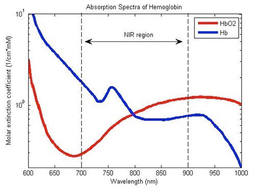
Figure 1: Pulse oximeters take advantage of differential energy absorption of deoxygenated hemoglobin (Hb) and oxygenated hemoglobin (HbO2) at red and infrared wavelengths. (Image source: Wiki Commons)
As shown in Figure 1, deoxygenated hemoglobin (Hb) absorbs more red light than infrared light, while oxygenated hemoglobin (HbO2) absorbs more infrared light than red light. Pulse oximeters compare absorption readings of deoxyhemoglobin at around 660 nm and oxyhemoglobin at around 880 nm to calculate SpO2. This differential measurement approach yields cleaner heart rate data than photoplethysmography because it is less sensitive to motion, noise, or other measurement artifacts. Although pulse oximetry is simple in concept, implementation presents multiple, interesting challenges.
Design challenges
Given the relatively low rate of change of blood flow, a typical pulse oximeter design can operate at correspondingly low acquisition rates. A typical design will drive the red and IR LEDs alternately at a low frequency and minimum duty cycle to minimize power consumption. Operation at a low duty cycle also permits baseline measurement of ambient light while both LEDs are turned off. In driving the LEDs, however, you need to minimize noise while delivering current pulses at precise levels appropriate to each type of LED. Furthermore, the timing between red and IR LED current pulses needs to be carefully controlled to maintain measurement integrity. Designs able to meet these requirements can be relatively complex.
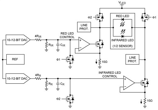
Figure 2: A typical pulse oximeter design uses separate low-noise current drivers to manage current driving red and IR LEDs, switching each alternately at an application specific duty-cycle and frequency. (Image source: Maxim Integrated)
To drive each LED, designers sometimes use separate current driver sub-circuits, each comprising a digital-to-analog converter (DAC) for current control, a filter stage for noise reduction, and an operational amplifier in the force-sense configuration (Figure 2). In turn, the output of each LED driver sub-circuit is switched into the associated LED at the selected frequency and duty cycle. In this configuration, the force-sense op amp configuration allows you to easily set the required gain with minimal additional components. In implementing this design, however, you need to carefully match the components in each path to minimize gain errors.
Variations of this overall design come with their own tradeoffs. For example, you can reduce complexity by using a single DAC, but possibly at the cost of additional noise. Higher noise generated on the output side can erode the signal-to-noise ratio (SNR) on the input side, degrading overall performance.
Pulse-oximeter designers measure red and IR light using two general approaches. One approach performs measurement primarily in the analog domain, using a dedicated analog-to-digital converter (ADC) for each wavelength, or a single high-resolution ADC synchronized with the LED drivers to measure results at each wavelength. Alternatively, you can perform measurements primarily in the digital domain. This approach simplifies hardware design, with the trade off being a modest increase in software complexity. At the heart of either approach, a transimpedance amplifier (TIA) converts photodiode output current to voltage for measurement by the ADC (Figure 3).

Figure 3: Pulse oximeters sense transmitted or reflected light using a single photodiode and associated signal chain comprising a transimpedance amplifier, filter, programmable gain amplifier (PGA), and analog-to-digital converter (ADC). (Image source: Maxim Integrated)
In a pulse oximeter, the signals of interest will generate relatively small photodiode current output, particularly compared to the current generated by ambient light sources. To help maximize SNR in this environment, the TIA itself needs to exhibit very low input current and noise. A high-pass filter is typically used to remove the ambient source component of the signal. Finally, a programmable gain amplifier is set to use the ADC's full dynamic range for optimum signal conversion resolution.
Along with careful design of LED output and photodiode input circuits, pulse oximeter designs require appropriate mechanical placement of the LED devices relative to the photodiode. In fact, pulse oximeters measure light output using two different physical configurations. Devices designed to attach to a finger or earlobe measure transmission of red and IR light. In these devices, the LEDs and photodiode are placed on opposite sides, typically contained in opposing arms of a clip. LEDs located in one arm of the clip shine light through the body part while a photodiode located in the opposing arm reads transmitted light levels.
In contrast, devices designed to be worn on a wrist or placed against a patient's forehead rely on reflectance of red and IR light. In these devices the LEDs and photodiode are both on the same side of the device in order to contact the skin. Reflectance HRMs offer more flexibility for the user because they can be placed against any sufficiently flat skin area. For the designer, however, this approach requires careful positioning of the LEDs and photodiode relative to each other to optimize reception of the red and IR light as each wavelength is reflected from blood flow passing beneath the skin surface.
Integrated solution
The seeming simplicity of the differential measurement method used in pulse oximetry belies the complexity of a combination of exacting analog and mechanical design requirements. Rather than deal with mechanical issues and critical LED output and photodiode input circuit design, developers looking to add HRM functionality to a product can do so with relatively little effort by dropping the Maxim Integrated MAX30102 into their product designs.
The MAX30102 is a self-contained module that meets the electronic and mechanical requirements described earlier. Along with the electronics for low-noise LED current management and photodiode signal acquisition, it includes red and IR LEDs and a photodiode, all optimally positioned for performing light-absorption measurements. You need add only a few external components to implement a pulse oximeter subsystem capable of providing heart rate data to a host processor (Figure 4).

Figure 4: The Maxim Integrated MAX30102 module includes LEDs, photodiode, and associated electronic circuits, requiring only a few additional components to implement a pulse oximeter. (Diagram drawn using DigiKey Scheme-it)
The driver current for the module's red LED and IR LED can be separately programmed from 0 to 50 mA. Further, the LED pulse width duration can be set from 69 μs to 411 μs to optimize the tradeoff between measurement accuracy and power consumption. An integrated proximity function further helps reduce power requirements by disabling light emission when the pulse oximeter's sensors are removed from the user's skin surface.
On the input side, the device integrates a complete SpO2 measurement subsystem that combines ambient light cancellation (ALC), a proprietary discrete time filter, and a sigma-delta ADC. You can program the 18-bit ADC's full-scale input range from 2 μA to 16 μA and its sampling rate from 50 samples per second to 3,200. The module's integrated temperature sensor allows for compensation of temperature-dependent measurement error.
Measurement process
The MAX30102 can operate in heart-rate mode as a conventional photoplethysmogram (PPG) using just the red LED, or in SpO2 mode using both red and IR LEDs. When the individual is at rest, heart-rate mode helps reduce power requirements. During periods of activity, however, motion artifacts can obscure pulse signals obtained with PPG methods. With its differential measurement approach, SpO2 mode provides stable measurements, but with an increase in both power requirements and operational complexity associated with driving both LEDs in the proper sequence.
To support alternating sequences of red and IR LED illumination, the MAX30102 provides two LED channels (Figure 5). Each channel can deliver a pulse of 69, 118, 215, or 411 μs duration with a preset time between pulses of 358, 407, 505 or 696 μs, respectively. Furthermore, sample rate implicitly sets an upper bound on the pulse width. For example, at the maximum sample rate of 3,200 sps, the pulse width is constrained to a maximum of 69 μs, resulting in the delay between red and IR pulses of 358 μs (see Figure 5). The selected pulse width also sets ADC resolution at 15 bits (69 μs pulse width), 16 bits (118 μs), 17 bits (215 μs), or 19 bits (411 μs).

Figure 5: The Maxim Integrated MAX30102 provides separate channels for driving red and IR LEDs with a specified pulse width, repetition rate, and time delay between alternating red and IR pulses. (Image Source: Maxim Integrated)
On the receive side, the MAX30102 integrates a first-in first-out (FIFO) buffer that stores up to 32 samples. Consequently, the host processor does not need to read sensor output data after each sample. Instead, the host can periodically acquire temperature data required for compensation, relying on the FIFO to meanwhile preserve heart-rate data while the MAX30102 continues to sample at the preset rate (Figure 6).
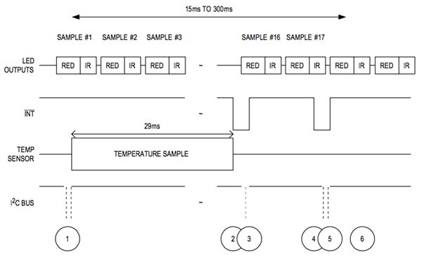
Figure 6: Maxim Integrated’s MAX30102's data buffer enables periodic temperature measurement without interruption of red and IR data acquisition at the preset sampling rate. (Image Source: Maxim Integrated)
As shown in Figure 6, a full pulse-oximetry sampling sequence begins with setting the device in SpO2 mode by writing 0x03 into bits 2:0 in the device's mode control register. As sampling proceeds, the sampling software can set the TEMP_EN bit in the device's temperature configuration register to initiate a temperature measurement (event "1" in the figure). When the MAX30102 completes the temperature measurement, it triggers the TEMP_RDY interrupt to alert the host ("2"). In turn, the interrupt is cleared when the host reads the temperature data ("3"). When the FIFO sample buffer reaches an "almost full" threshold (a value set in the device's configuration register), the device issues an interrupt ("4"), signaling the host to read the FIFO, which automatically clears the interrupt ("5”) and adjusts the FIFO read pointer to the location of the next new sample ("6"). Because FIFO pointers are adjusted with each FIFO read, this process can continue indefinitely until the application explicitly terminates SpO2 measurement.
Rapid development
For developers looking to accelerate HRM application development, Maxim Integrated provides its MAXREFDES117# reference design (See DigiKey article “MAXREFDES117#: Heart-Rate and Pulse-Oximetry Monitor”). Intended to help you gain familiarity with pulse-oximeter design, the reference design includes both hardware and software that together provide a complete standalone HRM solution. The kit's tiny 12.7 mm x 12.7 mm board includes the MAX30102 heart-rate/SpO2 sensor, the low-power MAX1921 step-down converter, and MAX14595 level translator (Figure 7). The MAX1921 step-down converter brings the system's supply down to the 1.8 V level required by the MAX30102. The MAX14595 level translator handles differences in logic level between the MAX30102 interface and the host board.
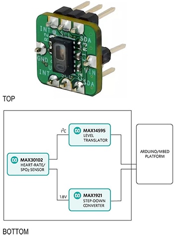
Figure 7: The Maxim Integrated MAXREFDES117# reference design includes a 12.7 mm x 12.7 mm board (top) that combines the MAX30102 with a step-down converter and level translator (bottom), allowing it to be used with popular development boards or any MCU that provides an I2C interface. (Image Source: Maxim Integrated)
The reference design board can be used with any MCU that provides an I2C interface. For designers looking for a quick start on application development, Maxim Integrated provides software library examples for the ARM® mbed or Arduino platforms. Using the sample software, the reference design board consumes less than 5.5 mW and achieves a level of accuracy comparable to a leading chest-strap HRM product (Figure 8).
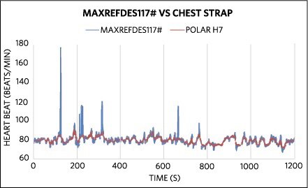
Figure 8: The Maxim Integrated MAXREFDES117# reference design provides hardware and sample software that delivers measurement accuracy close to the Polar H7 chest strap. (Image Source: Maxim Integrated)
Designed to help you get familiar with HRM applications, the sample source code actually provides a comprehensive HRM base library. The code includes a complete implementation of the SpO2 algorithm in the routine maxim_heart_rate_and_oxygen_saturation, which accepts the following inputs:
*aun_ir_buffer pointer to IR sensor data buffer
n_ir_buffer_length IR sensor data buffer length
*aun_red_buffer pointer to Red sensor data buffer
The routine maxim_heart_rate_and_oxygen_saturation updates the following parameters (provided as pointers in the function call argument list):
*n_spo2 Calculated SpO2 value
*ch_spo2_valid “1” if the calculated SpO2 value is valid
*n_heart_rate Calculated heart-rate value
*ch_hr_valid “1” if the calculated heart-rate value is valid
The Maxim Integrated sample code shows how to use the software library in an example application that displays acquired heart rate data on the developer's console. After initializing the MAX30102, the sample application starts by collecting samples for five seconds using routine maxim_max30102_read_fifo and then calculating heart-rate with the routine maxim_heart_rate_and_oxygen_saturation, continuing in an endless loop to collect samples and calculating heart rate until terminated by the user (Listing 1).
Copy
. . .
maxim_max30102_init(); //initializes the MAX30102
n_brightness=0;
un_min=0x3FFFF;
un_max=0;
n_ir_buffer_length=500; //buffer length of 100 stores 5 seconds of samples running at 100sps
//read the first 500 samples, and determine the signal range
for(i=0;i<n_ir_buffer_length;i++)
{
while(INT.read()==1); //wait until the interrupt pin asserts
maxim_max30102_read_fifo((aun_red_buffer+i), (aun_ir_buffer+i)); //read from MAX30102 FIFO
if(un_min>aun_red_buffer[i])
un_min=aun_red_buffer[i]; //update signal min
if(un_max<aun_red_buffer[i])
un_max=aun_red_buffer[i]; //update signal max
}
un_prev_data=aun_red_buffer[i];
//calculate heart rate and SpO2 after first 500 samples (first 5 seconds of samples)
maxim_heart_rate_and_oxygen_saturation(aun_ir_buffer, n_ir_buffer_length, aun_red_buffer, &n_sp02, &ch_spo2_valid, &n_heart_rate, &ch_hr_valid);
//Continuously taking samples from MAX30102. Heart rate and SpO2 are calculated every 1 second
while(1)
{
. . . // loop forever, repeating sequence above:
// read samples from fifo
// calculate heart rate
}
. . .
Listing 1: Maxim Integrated's sample code for the MAXREFDES117# reference design demonstrates how you can use simple calls to a pair of library function to obtain heart-rate and SpO2 data. (Code source: Maxim Integrated)
Conclusion
Heart-rate is an important indicator of an individual's health and fitness level. Growing consumer interest in measuring this vital statistic has made heart-rate measurement an important differentiator not only in fitness gear but also in mass-market wearables. Pulse oximetry provides a highly flexible solution for heart-rate measurement, but levies exacting requirements on electronic, mechanical, and software design. With the availability of the Maxim Integrated MAX30102 biosensor module and associated MAXREFDES117# reference design, you can implement a pulse oximeter with minimal additional hardware or software to virtually any product designed for fitness or every day use.

免责声明:各个作者和/或论坛参与者在本网站发表的观点、看法和意见不代表 DigiKey 的观点、看法和意见,也不代表 DigiKey 官方政策。


 中国
中国