Designs (830)
Demonstration circuit DC1198A-A features the LTM®4605EV, the high efficiency, high density switch mode buck-boost μModule® regulator. The LTM4605EV can regulate its output voltage from an input voltage above, below, or equal to the output. The input voltage range of DC1198A-A is from 4.5V to 20V with a preset output voltage of 12V. The rated load current is 5A, although derating is necessary for …
Demonstration circuit DC1194A features the LTM®8020, a 200mA DC/DC step-down μModule® regulator. The board is preset to deliver a 3.3V output at up to 200mA load current from an input voltage of up to 36V. The output voltage may be modified by simply changing one resistor.
Demonstration circuit DC1041A-A features the LTM®4601EV, a 12A high efficiency, high density switch mode step-down converter. The input voltage range is from 4.5V to 28V. The output voltage is jumper selectable for popular voltages from 0.6V to 5V. The PLLIN pin supports synchronizing the μModule® regulator to an external clock.
Demonstration circuit DC1084A-B features the LTM®4602HV, the high efficiency, high density step-down μModule® regulator. The input voltage range is from 4.5V to 28V. The output voltage is jumper programmable from 0.6V to 5V, refer to the step-down ratio curve in the LTM4602HV data sheet.
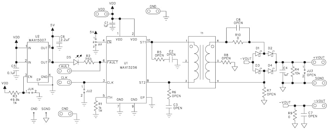
The MAX13256 evaluation kit (EV kit) is a fully assembled and tested PCB that contains the MAX13256 10W isolated H-bridge DC-DC converter. The EV kit operates from an 8V to 36V DC power source and the on-board 1:1 turns-ratio transformer from HALO sets the output voltage range from 6.8V to 34.8V with a 300mA current limit.
The LMZ23610/8/6 and LMZ22010/8/6 SIMPLE SWITCHER® power modules are easy-to-use DC-DC solution capable of driving up to a 10, 8 or 6 ampere load. They are available in an innovative package that enhances thermal performance and allows for hand or machine soldering. The LMZ23610/8/6 can accept an input voltage rail between 6V and 36V and the LMZ22010/8/6 can accept an input voltage rail between 6…
The LM5006EVAL evaluation board provides the design engineer with a fully functional buck regulator, employing the constant on-time (COT) operating principle. This evaluation board provides a 5V output over an input range of 6V to 75V. The circuit delivers load currents to 500 mA, with current limit set at a nominal 1 Amp.
This Synchronous Buck Evaluation Board features Microchip's 1A 1.4MHz synchronous buck regulator in two buck converter applications.
The Texas Instruments TPS62020 evaluation module (EVM) for low-power, high-efficiency, step-down converters helps designers evaluate this device. The EVM enables evaluation of different device modes and device performance.
This demonstration board is based on the ST1S12 family of synchronous step-down DC-DC converters optimized for powering low-voltage digital cores in HDD (hard disk drive) applications and is generally used to replace high-current linear solutions when power dissipation may cause high heating of the application environment.


