制造商零件编号 A000066
ARDUINO UNO R3 ATMEGA328P BOARD
Arduino
Arduino makes it easy to tinker with technology. It’s a family of microcontroller boards that let you sense the world around you and control electrical devices.
The word Arduino refers to several layers of the circuit prototyping process. The hardware, both the official Arduino boards and thousands of derivative Arduino-compatibles.
The software used to communicate with the hardware is called an Integrated Development Environment– the Arduino IDE. The programming language you’ll use is also called Arduino and is based on C++.
And Arduino also refers to the trademark of the Arduino corporation that manufactures official boards and maintains the open-source documentation that helps make the ecosystem free and easy to share.
Arduino is a huge global community, which means you can find a nearly infinite amount of inspirational projects, sample code, and answers to your questions online.
If you follow along with this series, you’ll do experiments to build up your skills and familiarity with the key concepts of controlling components with electricity, as well as coding in the Arduino language.
Here are the supplies I recommend for getting started with Arduino hardware prototyping:
You can also use circuit simulators like Tinkercad Circuits or Fritzing to get started without any hardware at all.
The board I recommend starting with is the Arduino Uno (1050-1024-ND), or compatibles such as the Adafruit Metro (1528-1214-ND), Sparkfun Redboard (1568-1977-ND) or Seeeduino (102010026-ND).
These beginner-focused boards have large labels to help you see what you’re plugging into the header pins along the edges, which connect to various pins of the microcontroller chip itself, which is a tiny computer running a program that we upload to it from a regular computer. On the board, you’ll also find a reset button, a power indicator LED, some LEDs to indicate when the board is sending and receiving data, and an LED wired to pin 13 for testing without having to plug anything into the board. The other components support the microcontroller and make it easy to wire up and program circuits without a degree in electrical engineering.
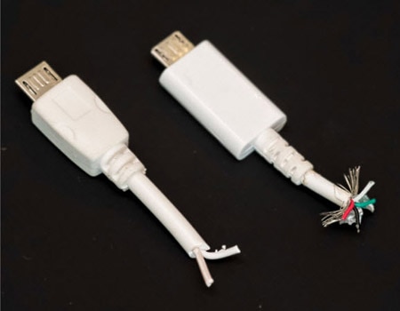
Make sure you’ve got the correct USB cable to connect your board to your computer. It needs to have the right connectors and be a data-capable cable, which looks the same as the charge-only type. There isn’t a simple way to tell them apart– a data-capable cable will allow your Arduino board to appear in your software’s Port menu, and a charge-only cable won’t. The best way to be sure is to purchase a cable you know is a data-capable cable.
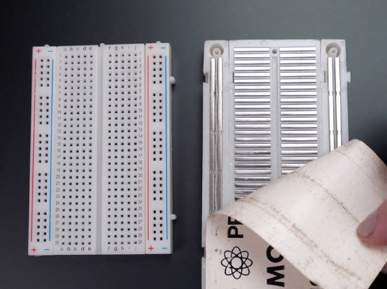
You’ll also need a solderless breadboard (1738-1326-ND). This device has metal strips inside and many holes that allow you to connect components quickly and easily. You can learn more about breadboards from the following video.
I like to connect the breadboard and the Arduino board with a mounting plate, so my circuits stay together better.
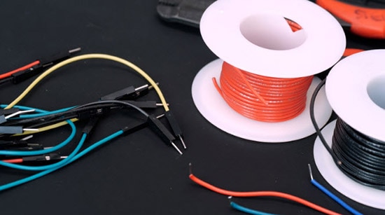
You’ll use some wires to connect to the Arduino: either some purpose-built breadboard wires (1528-1967-ND) or solid core hookup wire (1528-1743-ND) works fine too.
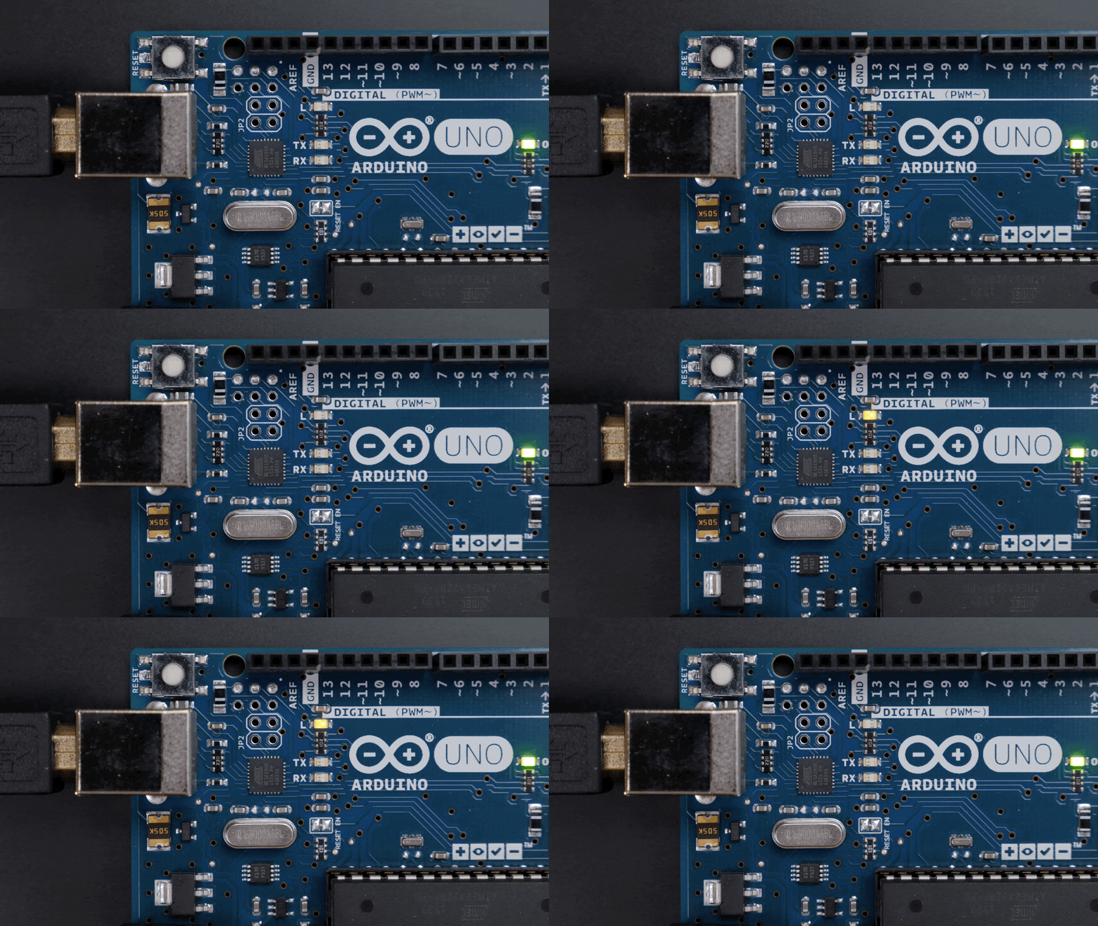
Before we get into the software, we can build a simple circuit with the program that comes on the board from the factory, which just blinks an LED connected to pin 13. See, pin 13 connects to the longer, positive leg of the LED, and the shorter, negative leg of the LED is connected to ground through this resistor, which helps limit the current to prevent the LED from burning itself out. We covered LED Basics in a previous tutorial if you want to learn more, but for this circuit, anywhere from 100 ohms to 1000 ohms will work great.
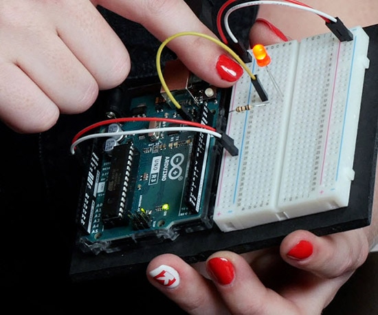
Connect 5V and ground from the labeled pins on the Arduino over to the bus bars on the solderless breadboard. These bus bars run the length of the breadboard on either side so you can easily access power and ground. For our circuit, it’s not strictly necessary to use the ground bus as an intermediary connection to the board’s ground, but it’s best practice to connect your bus bars whenever you’re prototyping.
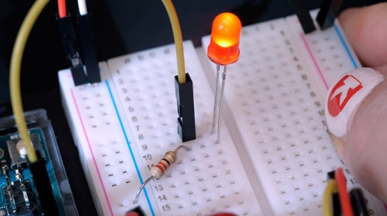
Once you’ve built this circuit, which you should always do with the power disconnected, you can go ahead and plug your board into the computer. Your new LED should blink in time with the tiny surface mount one on the board. If it doesn’t, double-check that your wires are all in the correct positions and that your LED isn’t backward. The connections are pretty small, so it’s super easy to plug a wire into the wrong row.

Once your LED is blinking, it’s time to dig into the program controlling it. The basic blink example is included in the downloadable Arduino software, which you’ll need to install on your computer. Open it up and look under File, Examples, 01 Basics, Blink.
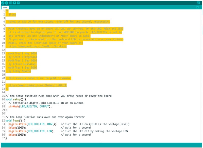
All the extra symbols you see are part of Arduino’s syntax, but don’t get intimidated. It takes time to learn to write proper code from scratch! I’ll break it down for you here, and you can always use the examples for reference as you level up.
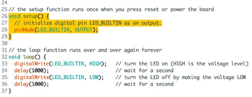
The first section is a block comment, followed by the code’s setup, which helps set up things your program will need later. It runs once when the program starts up. Our blink sketch’s setup configures pin 13 as an output, which prepares the board to send signals to it, rather than listen for input on this pin.

The main body of the program is inside the loop. This part of the code will execute on repeat, so long as the board has power. The colored text following double slashes are also comments to help make the program easier to understand.
The output command we’re using is called digitalWrite(), which is a function that sets a pin HIGH or LOW, on or off. To pause the program we’ll use delay(), which takes milliseconds. One second is 1000 milliseconds. So, to summarize, the program turns an LED on and off at one-second intervals. Try customizing this code by changing the delay values to two seconds (2000 milliseconds) and half a second (500 milliseconds).
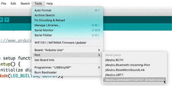
To program your Arduino board, make sure your USB cable is plugged in and select your board in the tools menu, then select your device from the port menu. If none of your ports are labeled in the menu, try unplugging your board, checking the Ports menu, then replugging your board and checking the Ports menu again to see which one appeared since you plugged it in. Then click the Upload button to transfer the Blink example code to the Arduino board.
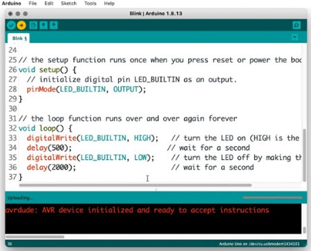
The LEDs labeled RX and TX will flash, and the software will show the message "Done uploading." Moments later the LED will begin blinking with your custom program.
If you’re uploading to an Arduino-compatible, but not Arduino-brand board, there may be an additional driver or board installation step before you’re able to see it in your port menu; refer to your product documentation to see what’s required.
Now that you’ve got a digital example working, it’s time to try something analog. Sure, blinking is great, but it can also tell the LED to be somewhere in between fully on and fully off. We can program fading effects. But only a few pins on the Arduino are capable of this analog-ish output. These pins are labeled on your board with a little squiggle (~) or other mark.
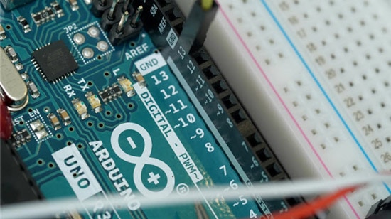
Unplug the Arduino before making any changes, then unplug the wire connected to pin 13 and move it to pin 9, which is marked as a PWM pin.
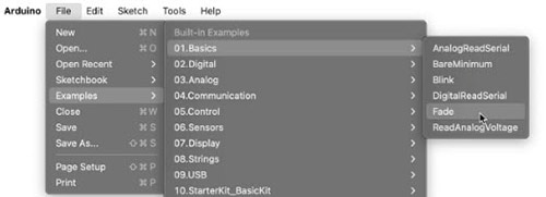
Open up the example in your Arduino software examples under File, Examples, 01.Basics, Fade. Plug in and upload the sketch to your Arduino Uno board and observe your LED fade on and off.
The Arduino board is only capable of generating digital signals (HIGH and LOW), but analogWrite(); simulates the appearance of brightnesses between on and off using pulse width modulation (PWM). The LED flashes on and off very quickly, and your eye interprets a dimmer light. The ratio of time the LED spends on vs. off determines how bright or dim the LED appears.
Let's look at the code to learn how this fading is achieved. You may wish to enable line numbers in the Arduino preferences in order to better be able to reference the different parts of the code.
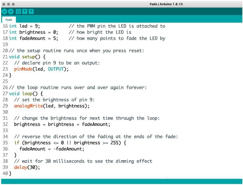
Lines 16 through 18 declare three variables used in the program. The setup configures pin 9 as an output on line 23. On line 29, the function analogWrite(); sets pin 9 to whatever the variable brightness is at the given time. On line 32, brightness is incremented by fadeAmount, which is 5.
Line 35 uses an if statement to check brightness using comparison operators. If brightness is less than or equal to (<=) zero, or (||) greater than or equal to (>=) 255. If the statement is true, the code inside is executed, otherwise, it's just skipped. So, this code increases brightness until it reaches or exceeds 255, then sets fadeAmount to -5 and decrements brightness until it reaches zero (or dips below zero). The delay at the end prevents the code from running so fast that you can't see the effect.
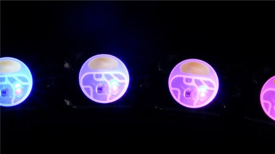
The fast flashing of PWM is why you can sometimes see LED lighting flicker when you record it on video, depending on your shutter speed. PWM is also used to allow for color mixing in an RGB LED. One LED of each color is set to its own brightness, and when they mix in a single package can form any color of light.
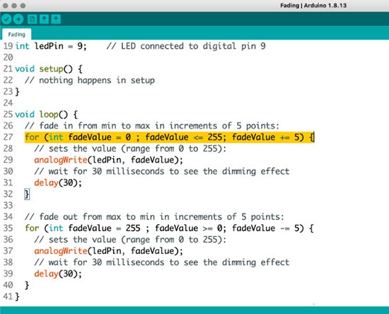
The last concept I’d like to introduce in this intro to Arduino basics is a for loop, also called a counting loop, which counts from an initial value to an upper limit. In this program (File, Examples, 03 Analog, Fading), we are counting from zero to 255 in increments of five, just like in our LED fading program from earlier, which shows there’s more than one way to write the same program.
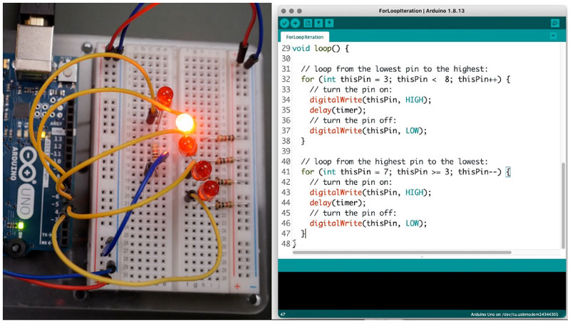
You can also wire up a few more LEDs and use a for loop to animate them– open up File, Examples, 05 Control, ForLoopIteration). After the for loop completes its count, the rest of the main loop executes, then starts over again.
Getting started with Arduino can be pretty overwhelming at first, but don’t forget that you can always look things up online when you get stuck. The Arduino site has an excellent Language Reference where you can find explanations and examples of every part of the code, and a community forum where you can get help with your own projects.