How to interface an IMU with an ESP8266
2021-03-31 | By Maker.io Staff
An IMU, or inertial measurement unit, can be a useful addition to all sorts of projects. IMUs typically combine accelerometers, gyroscopes, and sometimes magnetometers to measure the angular speed of a physical body. However, translating the readings from such an IMU sensor can be a challenging task. Because of that, this article employs a BNO085 based IMU breakout board. This board converts the values from different sensors and combines them to an easy-to-understand and beginner-friendly value, such as a rotation vector, that describes the orientation of the sensor board in three-dimensional space. This technique is useful for various applications such as flight-controllers, for example, in model aircraft.
Bill of Materials
Product/Where to buy
Connecting the IMU Breakout Board to the ESP8266
This step depends on the IMU board you choose and the requirements of your project. Many IMU breakout modules allow the users to select one of several communication options to interface the sensors with a microcontroller. You can get a heads up on different ways of interfacing sensors with an ESP8266 development board here. In this article, however, I decided to use the I2C bus for communications. This particular module, however, supports other communication options such as SPI and UART.
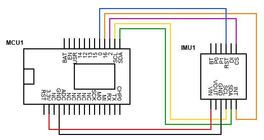
The following diagram shows how to connect the components for communicating over I2C:
Note that this device already includes appropriate pull-up resistors on the I2C lines (SDA, SCL), so it isn't necessary to add external ones. Different modules, however, might require external resistors to function as intended. Consult the datasheet of your module if you want to employ a different one in your project.
Furthermore, users can employ the P0 and P1 pins to select the communication mode of the IMU breakout board. If P0 and P1 are pulled low (or left floating), then the board defaults to I2C, which is what I wanted in this case.
It's possible to change the I2C address of the device by pulling the DI pin high in the I2C mode. If the pin is low (or floating), the device listens to address 0x4A. If the DI pin is high, the device will respond to 0x4B.
Testing the IMU
Getting the IMU to work with any ESP8266 based development board can be somewhat troublesome, especially over I2C. That is the reason I chose this setup. I wanted to document a few of my findings while working with the IMU and the ESP8266. For one, the official Adafruit library isn’t quite ideal for this task, as it needs too much memory, which renders it useless on many low-resource development boards. If you don’t want to manually implement the communications protocol of the sensor itself (the BNO085 in this case), we recommend you employ the Sparkfun BNO080 library instead. The BNO085 is backward compatible with the BNO080, and the library works perfectly fine. Here’s a short test script to get you up and running:
// Include the necessary libraries
// Wire handles the I2C communication
// The BNO080 library implements the communication protocol

#include <Wire.h>
#include "SparkFun_BNO080_Arduino_Library.h"

#define WARM_UP_TIME 150
#define IMU_ADDRESS 0x4A

// Create a new IMU object
BNO080 imu;

void setup()
{
  Serial.begin(9600);

  // Make sure to supply the correct pin numbers to the SDA and SCL pins!
  Wire.begin(4, 5);
  Wire.setClockStretchLimit(4000);

  // The ESP8266 seems to be unable to read data from the sensor without the
  // added clock stretch limit and if the sensor didn't have a short
  // 'warm-up' time to initialize itself.
  // Therefore, wait for a few milliseconds

  long start_millis = millis();

  Serial.println("Initializing sensor...");

  while(millis() - start_millis < WARM_UP_TIME)
  { }

  Serial.println("Ready!");

  Wire.flush();

  // Check if the IMU is available
  if (imu.begin(IMU_ADDRESS, Wire) == false)
  {
	Serial.print("Couldn't find the IMU at address ");
	Serial.println(IMU_ADDRESS);

	while(true)
	{ }
  }

  // Increase the I2C data rate to 400kHz
  Wire.setClock(400000);

  // Send requests to the IMU every 50ms
  imu.enableRotationVector(50);
}

void loop()
{
  // Check whether the sensor is ready to transmit data
  // This should happen roughly every 50ms (as defined above)
  if (imu.dataAvailable())
  {
	float i = imu.getQuatI();
	float j = imu.getQuatJ();
	float k = imu.getQuatK();
	float real = imu.getQuatReal();
	float acc = imu.getQuatRadianAccuracy();

	Serial.print(i, 2);
	Serial.print(",");
	Serial.print(j, 2);
	Serial.print(",");
	Serial.print(k, 2);
	Serial.print(",");
	Serial.print(real, 2);
	Serial.print(",");
	Serial.print(acc, 2);
	Serial.print(",");

	Serial.println();
  }
}
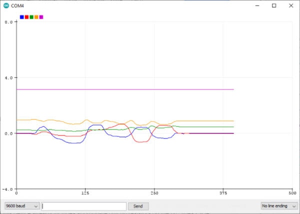
You can see the aforementioned warm-up time of the sensor in the setup method of the script. For that, the sketch acquires the time since it started in milliseconds, and then it waits in a while loop until the current time surpasses the warm-up time defined at the beginning of the script. Make sure to supply the correct SDA and SCL pins to the Wire library in the setup method. Then, the setup method sets custom values to the clock and clock stretch limit in the Wire library to enable communication between the ESP8266 and the IMU. Last but not least the start method enables the rotation vector readout on the IMU, and it requests data every 50 milliseconds. The loop method itself does nothing particularly interesting. It just checks whether the sensor is ready to deliver a result, and the loop method then receives the values from the sensor. In this example, the ESP8266 reads the rotation vector. You can visualize the results with the serial plotter of the Arduino IDE:

Summary
An IMU can be a useful addition in a wide variety of projects ranging from flight controllers for RC planes to security devices, for example, tilt-detectors. Typically, IMU breakout boards offer a good range of different communication methods they support. This makes it easy to choose the right one for the microcontroller in your project or according to your project requirements. This particular IMU board was a little more difficult to use with the ESP8266, as initially expected. The official Adafruit library didn’t seem to work very well for me. Instead, I employed the compatible Sparkfun BNO080 library for Arduino. This library, in conjunction with a short warm-up time for the sensor, made the IMU a useful addition to my portfolio of sensors.

Have questions or comments? Continue the conversation on TechForum, DigiKey's online community and technical resource.
Visit TechForum


 中国
中国