How to Connect Different External Modules to an Arduino
2020-12-02 | By Maker.io Staff
When working with an Arduino, users often want to use external modules for different tasks. That could be sensors for a thermometer, or a liquid crystal display, or connecting to a completely different computer or development board. Usually, they all similarly connect to the Arduino, and this how-to will introduce four common ways of connecting external hardware to your development board.
BOM
Using Your Hardware’s Interface
Before beginning, users need to find out what communication standard your external module uses. The best place to look is the device’s datasheet or manual (or looking at the input/output pins on the module itself). Devices that can interface via a serial connection usually have TX and RX pins, I2C compatible components often expose SDA and SCL connections, and SPI devices should have pins labeled MOSI, MISO, and SCK (sometimes also CLK or SCLK).
 Image source: Adafruit
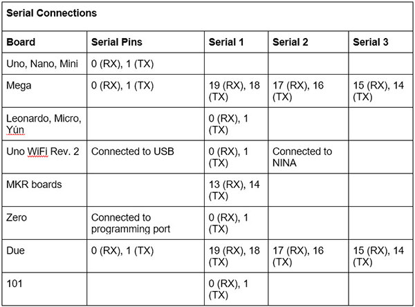
The next step after understanding how to connect with a particular device is to know where those pins connect to on an Arduino. The following table works as a reference:

Note that on the Arduino Uno, Nano, Mini, and Mega, pins 0 and 1 get used for communicating with the computer. Connecting anything to those pins can cause failed uploads. For more details, you can take a look at the official documentation.


Note how MISO, MOSI, and SCK are available in the same position on almost all Arduinos to allow the design of shields that work on every supported board.
A Brief Introduction to the Serial Port
As mentioned, the serial port is what a computer uses to communicate with an Arduino. It can also send messages to the Arduino and produce debug output. However, it’s possible to utilize the serial port for communicating with other development boards and modules.

As seen above, two Arduino boards are connected via their serial port. Note how the TX port of one Arduino connects to the RX port of the other one (and vice versa). Learn more by visiting the schematic on Scheme-It.
What is I2C?
In the I2C communication protocol, every connected device needs to have a unique address which you can usually find in its datasheet. The Arduino IDE comes with a standard library that assists in this process. Note that in some cases you’ll need pull-up resistors on the SDA and SCL lines to pull them high when they are not in use. However, many modules already have the appropriate resistors in place.

Many modules already come with onboard pull-up resistors so that users can directly connect it to the Arduino. Learn more by visiting the schematic at Scheme-It.
What about SPI?
In SPI, there is always a master device that controls one or multiple external slaves. As mentioned above, this typically requires three lines for this protocol.
The MISO line gets used by the slaves to send data to the master device. MOSI is for sending data to the slaves, and the CLK signal synchronizes all components. However, there’s an additional SS line per peripheral, which stands for slave-select. This enables the master to select the active peripheral to allow multiple devices to share the same three lines.

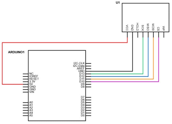
The example above shows how an external module can connect to an Arduino’s SPI pins. Learn more by visiting the schematic at Scheme-It.
Users will also have to find out what the maximum transmission speed of their module is, whether they have to send the data in reverse order (LSB first), and how the clock should behave. They then need to pass those values to the Arduino SPI standard library when you want to communicate with a module.
Device-Specific Protocols
As mentioned in the beginning, there’s also a fourth method for connecting peripherals to your Arduino. Some devices use none of the methods discussed so far. In those cases, the device’s datasheet will give particular information on what connections must be made and how to implement the communication protocol itself.
If it’s a popular part, like the DHT22 temperature sensor, there will most likely be pre-made Arduino libraries that you can use in your project. You can also have a look at the article “How to Use Serial EEPROM for Storing Data” for a more detailed example.

Have questions or comments? Continue the conversation on TechForum, DigiKey's online community and technical resource.
Visit TechForum


 中国
中国