Make an RFID Reader with an Arduino
2017-03-08 | By All About Circuits
License: See Original Project Arduino
Courtesy of All About Circuits
RFID (Radio-Frequency Identification) technology is in mobile phones, credit cards, pet tracking chips, toll booths, and in tags for just about everything sold these days. Like many technologies used in consumer-end devices, RFID began as a military application.
The origins of RFID technology go back to World War II, both the Allied and Axis powers’ air forces were using radar by 1935. Although radar was effective at detecting approaching aircraft, radar operators had trouble distinguishing friendly and enemy planes. The Germans solved this issue by rolling their planes as they passed into friendly radar range which would change the radio signal that bounced off of the planes, which was essentially the first passive RFID system.
Meanwhile, the British, in a top secret project headed by Sir Robert Alexander Watson-Watt (The man who discovered radar) developed the IFF system, which stands for “identify friend or foe.” The British put an IFF transmitter on each plane which would broadcast a signal letting their radar station know that they were friendly aircraft. The IFF transmitters were the first active RFID systems.
Fast forward to today and you’ll find RFID in just about everything! In this project, you’ll use an Arduino and an ID12LA RFID module to make your own RFID tagging system.
RFID Basics
Before we start wiring stuff, let’s brush up on our RFID knowledge. There are two distinctly different types of RFID technology: passive and active.
Passive RFID
A passive RFID system has an antenna and circuitry that houses a unique code, but has no power source. A passive RFID system requires a reader to induce current into the RFID tag’s circuitry, similar to how the German planes required radar to bounce off of them.
There are a variety of ranges and frequencies used for passive RFID, but the most common are:
- Low frequency: ~125 kHz. Typically has a range of a few centimeters
- High frequency: 13.56 MHz. Has a range of up to a meter
- Ultra-high frequency: ~865 MHz. Has a range of about 30 meters
Passive RFID has a very short range, but they are still very popular because they are inexpensive and they last a long time without service.
Inexpensive 125 kHz passive key tags that the ID12LA can interrogate. Image courtesy of RFIDTEK
Active RFID
Like the IFF transmitters on British fighter planes, active RFID systems require power to transmit their code. Active RFID systems have a much longer range than passive systems, some up to a few hundred meters. Active RFID usually operates at 433 MHz or 915 MHz.
There are two types of common active RFID systems: transponders and beacons.
A transponder tag is similar to the passive system in terms of the communication protocol. The reader will send a signal to the tag to ask for its code.
A beacon tag will do the opposite and send a signal every so often on its own—but this really cuts down on battery life.
In either passive or active systems, you can have a tag that is read-only or writable. Read-only means just that, you cannot change the tag's data. Writable means that you can choose what data to place within the tag.
An active RFID tag. Image courtesy of RFIDinsider.
Schematic and BOM
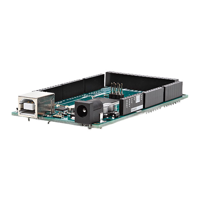
Now that the RFID lesson is over, let’s build something! We used an Arduino MEGA, but most Arduinos will work. Although the official ID12LA breakout PCB isn’t required, it makes the project much easier since the ID12LA’s pins can be tricky.
Hardware
- Arduino MEGA
- ID12LA
- ID12LA Breakout PCB (Or an RFID starter kit)
- Small Breadboard
- Some jumper wires
- Solder and Soldering iron
Software
- Arduino IDE
Communicating with the ID12LA with an Arduino
The ID12LA’s datasheet (PDF) is good to have handy. You can find the nitty-gritty details on All About Circuits if you’d like to know how the code works, but here’s what the code does on a more basic level:
- Monitor the serial buffer for available data.
- When data is present, read and save it with some validation to ensure communication integrity.
- Display the data to a serial monitor (primarily for initial setup) and compare tis tag to the saved tags.
- Perform an action (In this case, the action was to spit out data from the serial monitor).
Wiring it Up!
You can find the ID12LA’s pinouts on page 3 of the datasheet:
Follow the schematic below to connect the Arduino and the ID12.
An example on how to wire on a breadboard
RFID Applications
RFID with access control can be a dry subject — but with some imagination, you can tailor it to different ideas.
It does have some recreational applications, though. Take geocaching, for example, you can hide RFID tags that can open clues to other treasures.
If you want to go even further, active RFID will broaden the horizon. One application that sticks out is someone tagging all of their food and creating a database that gives recipes on what to make for dinner depending on what tags are in the fridge; overkill, but definitely cool! Have you made something interesting using RFID? Tell us about it in the comments!

Have questions or comments? Continue the conversation on TechForum, DigiKey's online community and technical resource.
Visit TechForum


 中国
中国