Make a Simple Electronic Die without a Microcontroller
2021-12-02 | By Maker.io Staff
License: See Original Project
Microcontroller projects can quickly become very complicated and difficult to understand, especially for beginners. Therefore, we’ve chosen to make a project here that doesn’t require an MCU. Instead, this electronic die project uses a few off-the-shelf digital logic ICs. The finished device generates a random number between zero and six. Then, the device shows the result on a bright and easy-to-read seven-segment display.
The finished device displays a random number once you press the button.
Bill of Materials
You’ll need the following components to build this project:
Component/Amount/Where to buy
- CD4543BE - (1)
- 7-segment display - (1)
- SN74HC163N - (1)
- Quartz-Oscillator - (1)
- 150 Ohm Resistor - (7)
- 74HCT00N - (1)
- Tactile push button - (1)
- 1M Ohm resistor - (1)
- 6” M/M Jumper Wires - (1)
- Solderless Breadboard - (1)
The Electronic Circuit
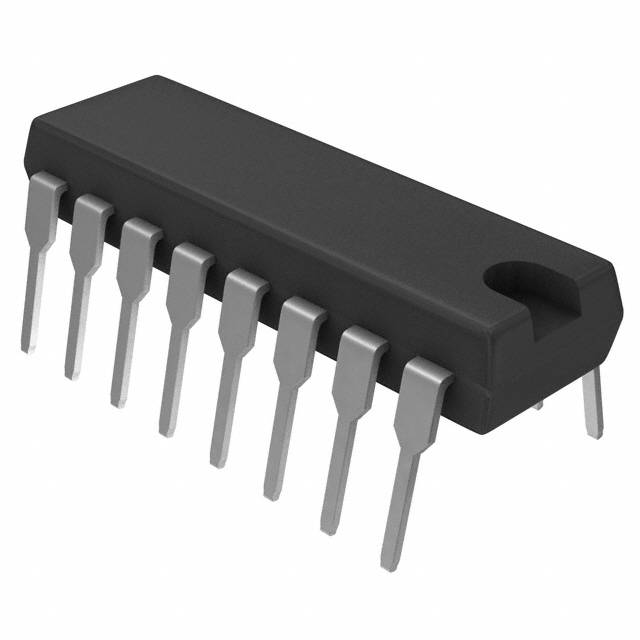
The electronic circuit diagram might look complicated at first, but it is composed of only three ICs and a single quartz-oscillator:
The finished circuit diagram of the simple electronic die.
As you can see, I laid out the components according to their function in the finished design. On the left, you can see the oscillator. The adjacent push button allows the users to generate a random number. The two stacked ICs in the middle select the random number, and the third IC on the right of the diagram displays the calculated number.
It’s important to note that you have to connect ENT and ENP pins of the SN74HC163N to the positive supply to enable the chip. Similarly, tie the CD4543BE’s LD pin to +5V and the BL pin to GND. If you’re using a common-cathode LED display, as I do in this example, you’ll also have to connect the PH pin to GND. In case you decide to use a common-anode LED screen, attach the PH pin to +5V.
How This Design Works
In the introduction, I mentioned this circuit generates random numbers and displays the result to the user. However, that’s not entirely correct. Computers and integrated circuits can’t generate random results under normal operating conditions. Instead, the silver quartz oscillator generates a steady clock input, and the SN74HC163N counter IC increases its internal count by one with every clock pulse. It does this continuously. However, note that I connected the B and C output of the counter IC to the 74HCT00N NAND-gate. When the B and C outputs go high simultaneously, the counter resets itself. Therefore, the reset happens when the counter IC reaches six.
Either way, the push-button controls the clock input to the counter IC. As long as the user doesn't press the button, the button connects the IC's clock input pin to GND. The counter IC retains its internal state while the clock is low. Once a user presses the button, they connect the IC's clock input to the quartz oscillator, thus advancing the counter's internal state. The random generation effect comes from the fact that the human input will be fairly random. That is because you will have a hard time pressing the button at exactly the same intervals each time you generate a number. Therefore, the counter IC will stop counting at a seemingly random position, and the finished circuit will display a pseudo-random number that you can use in your board games, for example.
You can effortlessly assemble this project on a solderless breadboard with the help of a few jumper wires. Note that I used different resistors to reduce the display brightness, as it's easier to take pictures of the finished product that way.
As mentioned, the silver quartz-oscillator generates a stable clock input for the counter. In this example, I used a 14 MHz clock signal. However, you could use pretty much any frequency as long as you stay below 25 MHz. Note that other versions of the SN74HC163N chip could have a different maximum supported clock frequency. Besides those two components, the circuit also contains a CD4543BE chip. This integrated circuit drives the seven-segment display.
In this project, I feed the output of the counter IC directly into the seven-segment controller. It’s also worth noting that I had to tie the CD4543BE’s PH pin to GND as I used a common-cathode LED display. If you’re using a common-anode display, connect the display controller’s PH input to +5V instead.
Summary
This simple project can generate pseudo-random numbers without the need for a complicated and expensive microcontroller. The quartz-oscillator creates a stable clock input signal for the counter IC. The counter IC increases its internal count once the user presses the push button. Once released, the IC stops counting, and the LED display controller IC shows the number on the seven-segment display.

Have questions or comments? Continue the conversation on TechForum, DigiKey's online community and technical resource.
Visit TechForum


 中国
中国