


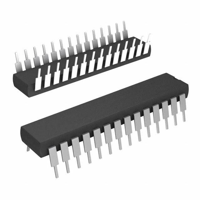
制造商零件编号 A000066
ARDUINO UNO R3 ATMEGA328P BOARD
Arduino
License: None
Editor’s Note: This two-part series shows how to turn an interesting valise and an even more interesting set of defunct vacuum tubes and tricolor LEDs into an utterly mesmerizing audio-frequency-synched visual array. Part 1 focused on the initial hardware setup. Here, Part 2 considers how we might enhance our Audio-Reactive Artifact’s capabilities using an envelope generator and an electret microphone.
In Part 1, I introduced my Audio-Reactive Artifact hobby project, which boasts a cornucopia of defunct vacuum tubes illuminated from below with tricolor WS2812B LEDs in the form of NeoPixel strips and rings from Adafruit, all presented in a small faux-antique valise (Figure 1).
Figure 1: Presented in a small faux-antique valise, the Audio-Reactive Artifact boasts a cornucopia of defunct vacuum tubes illuminated from beneath by tricolor NeoPixels. (Image source: Max Maxfield)
As discussed in my original blog, the initial incarnation of the project is powered by an Arduino A000066 Uno R3 development platform for the ATMEGA328P microcontroller from Microchip Technology. Since the point of the exercise is for the system to respond to sound, I also used a microelectromechanical systems (MEMS) microphone breakout board (BOB). Specifically, the BOB-09868 from SparkFun Electronics.
If all we wished to do was make all of the tubes light up with their brightness controlled by the amplitude of the audio signal, then we could simply connect the output from the microphone directly to one of the Arduino’s analog inputs.
The raw audio signal will be centered on a direct current (DC) bias (DCbias). In the case of the BOB-09868, this will be half of our circuit’s 3.3 volt supply voltage, so the DCbias will be 1.15 volts. As per SparkFun’s website, “When held at arm’s length and talked into, the amplifier will produce a peak-to-peak output of about 200 [millivolts] mV” (Figure 2).
Figure 2: When powered from a 3.3 volt supply, the raw audio output from the BOB-09868 will be 200 mV peak-to-peak (200 mVpp) centered on a 1.15 volt DCbias. (Image source: Max Maxfield)
What this means is that, if we wish to use this audio source “as is”, then we are going to have to perform some jiggery-pokery in the software. Of course, the Arduino will convert the readings from the analog input into digital values between 0 and 1,023, but let’s think in terms of voltages for this portion of our discussion. First, our program will have to “rectify” the input signal Vin such that we take any value below the DCbias and “reflect it” above the DCbias. Also, we need to remove the DCbias. This means that for any audio value Vin >= DCbias, we will convert this to Vin - DCbias. By comparison, for any audio value Vin < DCbias, we will convert this to DCbias - Vin.
Of course, there’s also the problem that we can be reading the analog signal at any point in its cycle. Consider the “max amplitude” portion of the waveform shown in Figure 2. When we read from the analog input, the chances are high that we won’t be sampling the signal as it hits its maximum value. There’s a batting chance that the signal will be crossing the DCbias centerline when we take our sample, which we would regard as being zero amplitude.
One way around this is to take a series of readings in quick succession and use whichever value is the largest. What would be better, of course, would be to have some way to access the “envelope” of the audio signal, by which we mean a smooth curve outlining the extremities of its waveform (Figure 3).
Figure 3: In the context of an oscillating signal, the term “envelope” refers to a smooth curve outlining the extremities of the waveform. (Image source: Max Maxfield)
If we had some way to generate a signal corresponding to the upper envelope in Figure 3, then all we would need to do would be to read this value via the Arduino’s analog input. To achieve this, we need a hardware circuit that can rectify the signal and then “smooth” it by just the right amount (Figure 4).
Figure 4: First-pass implementation of an envelope generator circuit. (Image source: Max Maxfield)
In this circuit, diode D1 acts as a half-wave rectifier. We could use a generic 1N4001, or we might opt for a small signal diode like a 1N4148. Note that we might need to tweak the various resistor and capacitor values while looking at an oscilloscope until we achieve the desired response.
As we previously discussed, using the output from the microphone either directly or via our envelope generator would allow us to control the brightness of all the tubes (in the form of the LEDs underneath them) as a function of the audio signal’s amplitude. But what if we want to be a little more sophisticated, such as using different colors to reflect the different frequency components in the audio stream?
One solution would be to implement a fast Fourier transform (FFT) algorithm in software, but the math makes my brain hurt. The solution I opted for in the case of my Audio-Reactive Artifact was to feed the output from the microphone into an 8-pin, 7-channel COM-10468 audio tone processor chip (better known as the MSGEQ7) from SparkFun Electronics, and then connect the output from this chip to the Arduino (Figure 5).
Figure 5: The Audio-Reactive Artifact is powered by an Arduino Uno R3 in conjunction with a BOB-09868 MEMS microphone and a COM-10468 audio tone processor. (Image source: Max Maxfield)
As discussed in Part 1, the COM-10468 constantly monitors the audio input stream and splits it into seven frequency “buckets.” At any time, the Arduino can latch the current relative frequency amplitudes by pulsing the RESET signal and read them out as analog values by pulsing the STROBE signal.
Of course, it’s still necessary to create the software that reads the frequency amplitude values from the COM-10468 and lights the appropriate tubes, but that’s the fun part. In the case of my Audio-Reactive Artifact, I have to say that I’ve been delighted with the result. When I bring a music source—like my smartphone—close to the Artifact, anyone in the vicinity goes “Ooh” and “Aah” in a very satisfying way. On the other hand...
A Smarter Artifact
With my current setup, I do have to adjust the volume of my smartphone and/or its proximity to the artifact to achieve the loudest “Oohs” and “Aahs.” What I really want is a system that’s a little more intelligent. At one extreme, if the room is perfectly quiet and I snap my fingers, I would like the artifact to flare up brightly. At the other end of the spectrum (no pun intended), if I crank up my music source to full rock-and-roll volume, I don’t want the artifact to simply saturate full-on, but rather to continue to respond to the audio signal in a meaningful way.
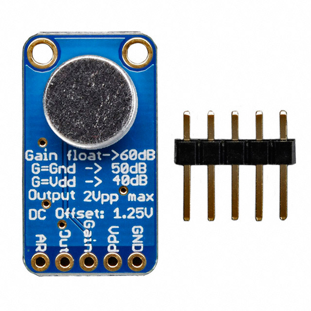
I think I’ve found the solution in the form of the 1713 electret microphone BOB from Adafruit (Figure 6), which features the MAX9814 amplifier chip from Maxim Integrated. The great thing about this amplifier is that it is equipped with automatic gain control (AGC), which employs closed-loop feedback to maintain a suitable average signal amplitude at the output, irrespective of variations of the average signal amplitude at the input.
Figure 6: The MAX9814 amplifier chip on Adafruit’s 1713 electret microphone BOB is equipped with AGC which enables the system to work with a greater range of input signal levels. (Image source: Adafruit)
Now, before we proceed, there is a slight issue with this BOB in that its output is 2 Vpp with a 1.25 volt DCbias, but the MSGEQ7 requires no more than 300 mVpp. Happily, this is easily addressed by front-ending the MSGEQ7 with a simple voltage divider circuit (Figure 7).
Figure 7: In addition to the COM-10468 audio tone processor, the enhanced Audio-Reactive Artifact employs a MAX9814 electret microphone BOB and an envelope generator. (Image source: Max Maxfield)
If we were to use the MAX9814-based BOB as is, then its default gain would be 60 decibels (dB) (1000). However, this BOB also has a master GAIN control input. If we drive this input with one of the Arduino's digital pins that has its mode set to OUTPUT, then driving the pin LOW or HIGH will cause the BOB to change its gain to 50 dB (~316) or 40 dB (100), respectively (setting the Arduino's pin mode to INPUT will return the BOB to using its default 60 dB gain).
Of course, for the Arduino to know what it needs to do, it has to have some clue as to what is coming out of the microphone BOB. This is where our envelope generator comes in. By periodically sampling the signal and keeping track of its recent history - perhaps by maintaining a rolling average - we can determine the overall current state of the output from the microphone and use it to control the gain.
If the master gain is currently set to 40 dB, for example, and the audio output from the BOB is constant and insignificant, which means our vacuum tubes will be dark and sad, then our program may decide to increase the gain to 50 dB or 60 dB. Alternatively, if the gain is currently set to 60 dB and the output from the BOB is a constant 2 Vpp, which means our vacuum tubes are going to be fully illuminated all the time, then our program may decide to drop the gain to 50 dB or 40 dB.
Recommended Reading
Conclusion
My next step will be to create a breadboard prototype of the enhanced system discussed here to provide a proof of concept. In the fullness of time, I’m planning on creating a standalone board that has the microphone on one side and all of the other components on the other, thereby making it easy to deploy in a variety of future audio-reactive gadgets and gizmos. In addition to the microphone, this board would also feature the COM-10468 audio tone chip along with the voltage divider and the envelope generator components. But that will be a blog for another day. In the meantime, as always, I welcome your comments, questions, and suggestions.

Have questions or comments? Continue the conversation on TechForum, DigiKey's online community and technical resource.
Visit TechForum


 中国
中国