


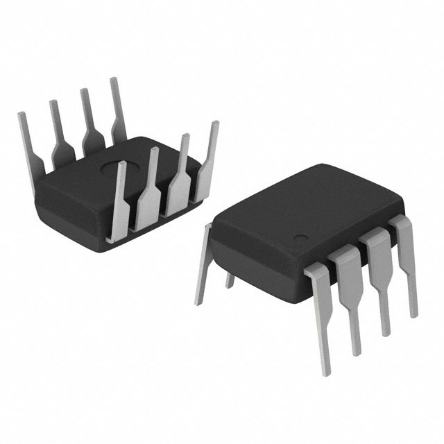
制造商零件编号 ATTINY45-20PU
IC MCU 8BIT 4KB FLASH 8DIP
Microchip Technology
License: General Public License Arduino
About two months ago I decided it was time to make a microcontroller controlled project without a development board. So, I picked a relatively simple game (Connect 4) and started looking into an SMD component based way to run it.
If you want to build this project for yourself all of the EDA and code files can be found in my GitHub repository.
Component Choice:
I quickly settled on the ATtiny line because they are small and can be programmed with the Arduino IDE as long as you have a serial programmer (an Arduino Uno/Mini can be programmed to turn into a temporary serial programmer).
I chose the ATtiny 45 because it was available in an eight pin DIP package which makes it really easy to program and prototype since it fits nicely into a breadboard and can then be transferred to a PCB mounted socket. The ATtiny 25/45/85 line also supports 16 MHz clock speeds and PWM signals which are required for running addressable LEDs. While it has only 6 GPIO pins, the ATtiny 45 can support PWM on four and analog on four.
This project uses only one PWM pin for an array of addressable LEDs and one analog pin to read all five input buttons.
Above is the test circuit I used to program the ATtiny and test the code and wiring before ordering the PCB.
For this project both the ATtiny 45 and 85 could be used. Note that the code uses at least 75% of the ATtiny 45’s 256 bytes of EEPROM so go with an ATtiny 85 if you plan to expand the code to add auto win detection or some other, more complex functionality.
Above is the PCB. Note the 470 Ohm resistor protecting the first LEDs signal input and the 0.1 uF capacitor filtering the power to the ATtiny.
To display the game I chose to go with a six by seven unit matrix of addressable RGB LEDs. I chose the WS2813 LEDs because they are small (5 mm x 5 mm), only require a specific implementation of PWM to control which can be easily run on the ATtiny with the help of a library.
The LEDs have been arranged into a two dimensional matrix with the signal from the last LED of each row connecting to the first LED of the next row. This makes it easier to directly translate a two dimensional array handling the game board into the pattern displayed by the LEDs that it would be if the path snaked back and forth or vertically.
Above is the board view of the PCB showing all trace connections.
While testing, I found that the two most popular addressable LED libraries (FastLED and Neopixel) use too much of the memory on the ATtiny 45, so I use the FAB_LED library instead.
While it does not technically support the WS2813 because it hasn’t been updated since 2015, FAB_LED does support the WS2812b which uses the exact same protocol.
Above is the PCB mid game. Note the colors blur on camera; In real life the LEDs glow with vibrant red and yellow colors.
As inputs I used five SMD push buttons which I wired with outputs in parallel connected to resistors of different values. This created a series of different valued voltage dividers which, when activated by a button press, could be read by the analog pin of the chip.
To provide the LEDs and ATtiny 45 with power I decided to use a standard micro USB cable for 5V input. The repurposed connector also has the benefit of fitting thinner breadboard wires so power could be routed from almost any 5V source as long as that source can be interfaced directly or indirectly with a breadboard.
Above is a close up of the micro USB connection.
Note: the design could easily be updated to use a USB C or any other connector with at least two pins instead.
Programming:
I programmed the ATtiny using the Arduino IDE and an Arduino Uno programmed as an ISP programmer.
The code can be broken down into three main parts: the definitions, the loop, and the abstractions.
Note: you will notice that I use uint8_t and uint16_t variables instead of int for most numerical variables. This is to save space since a uint8_t only takes up 1 byte and the uint16_t only 2 compared to the 4 bytes of an standard int. This is especially useful for the two dimensional array I used to keep track of the connect 4 game.
In the definitions section I have:
The FAB_LED setup which provides all of the definitions and variables used by the library.
  // RGB LED library
#include <FAB_LED.h>

  // Declare the LED protocol and the port
ws2812b<D,0>  strip;

  // How many pixels to control
const uint8_t numPixels = 43;

  // How bright the LEDs will be (max 255)
const uint8_t maxBrightness = 10;

  // The pixel array to display
grb  pixels[numPixels] = {};

  // whether the LED array needs to be updated
bool LEDchange = true;
The variables I use for button inputs.
  // Analog pin to read the buttons.
int analogpin = A3;
  // The last time the output pin was sampled.
long timer = 0;
  // Number of millis/samples to consider before declaring a debounced input.
int16_t debounce_count = 50;
  // Stores the current analog value on the button input pin.
int16_t ButtonVal;
  // whether the code is ready for a new button input
bool buttonDebounce = true;
The variables used run Connect 4.
  // Need to set up with all zeros. Then a red piece can be 1 and a blue piece can be 2. (array[row][column])
uint8_t gameBoard[6][7] = {
  {0, 0, 0, 0, 0, 0, 0},
  {0, 0, 0, 0, 0, 0, 0},
  {0, 0, 0, 0, 0, 0, 0},
  {0, 0, 0, 0, 0, 0, 0},
  {0, 0, 0, 0, 0, 0, 0},
  {0, 0, 0, 0, 0, 0, 0}
};
  // The position from left to right of the piece currently waiting to drop (range: 0 to 6).
uint8_t dropPosition = 0;
  // The status of the game. 0 = error, 1 = player 1 turn, 2 = player 2 turn, 3 = player 1 win, 4 = player 2 win.
  // Also controls the color of the status LED which is LED #43.
uint8_t gameStatus = 1;
  // Stores the game defined state of the button input.
uint8_t buttonState = 0; // 0 = no input, 1 = up arrow, 2 = down arrow, 3 = left arrow, 4 = right arrow
  // Whether the hanging piece is showing or hidden (for a blink animation).
bool hangBlinkOn = true;
  // Timer for the hanging piece blinking animation.
long hangBlinkTimer = 0;
  // blink duration.
uint16_t blinkLen = 800;
And finally the setup function to clear any ghost values on the LEDs and set up the analog pin.
void setup()
{
    // reset the LEDs
  strip.clear(2 * numPixels);
    // setup the pin for button inputs
  pinMode(analogpin, INPUT);
}
The loop runs the game, updates the LEDs, and keeps track of user input by calling functions from the abstraction section.
The loop contains:
The button detection function which checks for button updates and includes a half second debounce delay to prevent accidental double clicks. It uses the internal clock of the ATtiny so there is no need for artificial delays.
if (millis() != timer && buttonDebounce) // If we have gone on to the next millisecond and have no debounce needs.
  {
    ButtonCheck();
    timer = millis();
      // If the debounce of 500 milliseconds has been reached.
  } else if (millis() > timer + 500)
  {
    // debounce has been met so it is reset.
    buttonDebounce = true;
  }
The button action handler is what runs the functions assigned to each button if they have been pressed.
switch (buttonState)
  {
    case 1:
        // Write the pixel array red
      // This button does nothing and is included primarily
      //to allow more complex games to be programed into the board.
      LEDchange = true; // LEDs have changed
        // task complete
      buttonTaskComplete();
      break;
    case 2:
        // drop the current hanging piece
      dropPiece();
        // task complete
      buttonTaskComplete();
      break;
    case 3:
        // move hanging piece to the left.
      moveHangingPiece(false);
        // task complete
      buttonTaskComplete();
      break;
    case 4:
        // Move hanging piece to the right.
      moveHangingPiece(true);
        // task complete
      buttonTaskComplete();
      break;
    case 5:
        // clear the game board
      resetGame();
      LEDchange = true; // LEDs have changed
        // task complete
      buttonTaskComplete();
      break;
  }
The hanging piece blink section is what blinks the hanging piece to differentiate it from the pieces which have already been placed on the board. It also uses the internal clock.
if (millis() > hangBlinkTimer + blinkLen)
  {
    // Set hangBlinkOn to its inverse causing it to blink.
    hangBlinkOn = !hangBlinkOn;
    hangBlinkTimer = millis();
    LEDchange = true; // LEDs have changed
  }
The draw section is what updates the grid of LEDs every time a part of the game changes. It first draws all placed pieces and then overwrites the displayed image with the blinking hanging LED. This section also controls turn indicator LED.
if (LEDchange)
  {
       // Update the LED control array with game board.
    convertGameToLightList();
      // Update the hanging piece. Lights up the hanging LED in it's current spot.
      // (Note: haning LED is not represented on the game board)
    if(hangBlinkOn)
    {
      if(gameStatus == 1)
      {
        pixels[dropPosition].r = maxBrightness;
        pixels[dropPosition].g = 0;
        pixels[dropPosition].b = 0;
      } else if (gameStatus == 2)
      {
        pixels[dropPosition].r = maxBrightness;
        pixels[dropPosition].g = 8; // could also be maxBrightness - 2
        pixels[dropPosition].b = 0;
      }
    } else
    {
      pixels[dropPosition].r = 0;
//      pixels[dropPosition].g = maxBrightness/2;
      pixels[dropPosition].g = 0;
      pixels[dropPosition].b = 0;
    }
//      // Update status LED.
//      // Controls color of LED 43.
    if(gameStatus == 1)
    {
      pixels[42].r = maxBrightness;
      pixels[42].g = 0;
      pixels[42].b = 0;
    } else if (gameStatus == 2)
    {
      pixels[42].r = maxBrightness;
      pixels[42].g = 8; // could also be maxBrightness - 2
      pixels[42].b = 0;
    } else
    {
      pixels[42].r = 0;
      pixels[42].g = maxBrightness;
      pixels[42].b = 0;
    }
      // Display the pixels on the LED strip
    strip.sendPixels(numPixels, pixels);
      // reset change
    LEDchange = false;
  }
The final section is the abstraction functions. These are all used by the loop but have been separated from it either because they are used in multiple places or simply to make the code easier to read.
Here is a list of them:
And that’s it! We now have a fully functioning game of connect 4 that fits into a pocket and can be powered from any USB power source.
Future Modifications:
Simple code modifications that could be made include:
On the hardware side, this project has been designed to leave room for modification in the future. There are 4 free pins on the ATtiny chip and the use of addressable LEDs means the grid or set of indicator LEDs could be expanded significantly.
Other possible modifications include adding sound generation for sound effects, adding more buttons, or simply making a set of hot swappable ATtiny chips to act as game cartridges for the board.
I hope you gained some inspiration from this project.
Happy making!
A note on buying WS2813 LEDs: There are actually two versions of the WS2813. The one linked to this article is the newer one which includes a backup output along with the backup input of the original. My design works with both but you will need to add the backup signal traces if you want to take advantage of them.

Have questions or comments? Continue the conversation on TechForum, DigiKey's online community and technical resource.
Visit TechForum


 中国
中国