制造商零件编号 SC0915
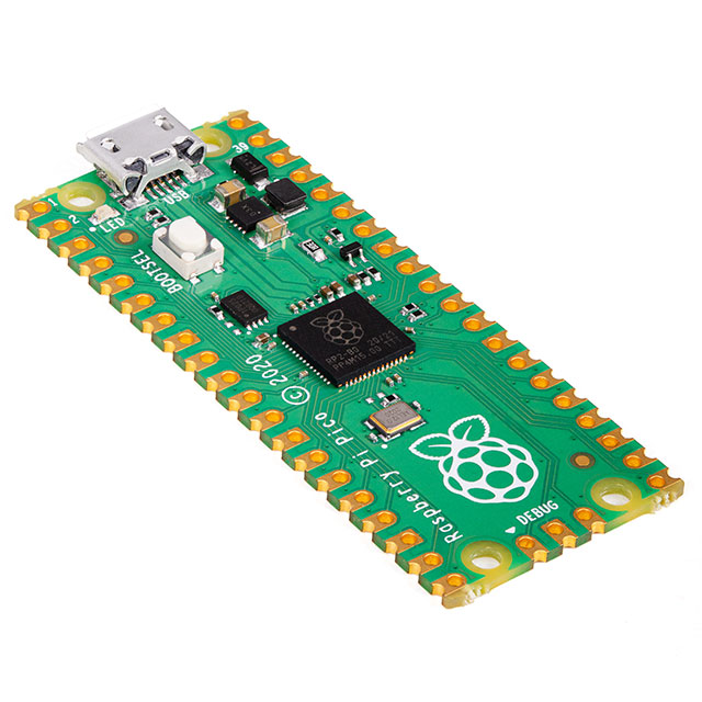
RASPBERRY PI PICO RP2040
Raspberry Pi
License: General Public License Raspberry Pi SBC
Hi! I’m a robotics engineering student who types a lot of math filled notes in text editors and, after over a year of online school, have finally gotten tired of Googling special characters mid-lecture to copy and paste every couple seconds.
To solve my problem I spent a month designing, building, and programming a simple, RP2040 based keypad with the ability to type over 100 unique characters, words, or keystroke shortcuts.
Here is a short video overview of the device and how I put it together:
Now that you have seen the overview here are the details:
The keypad uses ten Cherry MX keys, a 100 kΩ potentiometer, an SSD1306 based 128x64 pixel monochrome OLED screen, and the new Raspberry Pi Pico. I selected the Pico because it has USB 1.0 support, a lot of gpio pins in a small package, and is only $4 (as of the posting date of this project). The Cherry keys were selected because I like the feel of a full size mechanical keyswitch, the potentiometer because it is an easy way to get input for scrolling functionality, and the OLED screen because it provides a good image, is compact, and has existing libraries in CircuitPython. The keypad is built with a custom designed case and two layer PCB which were both created in Fusion 360. I printed the case in white PLA and ordered the PCB from an online manufacturer.
Using the keypad is easy, simply plug it in, wait for it to boot up in a couple seconds, and it’s ready to use! The potentiometer controls which key mapping is active and the OLED screen displays the current key information so you never forget what each of the ten keys does for each key mapping.
Since it uses the USB HID library, the Pico is able to simulate the pressing of any keys on a US keyboard. That means that it can type letters, words, or keystroke shortcuts like ctrl+c (copy). Since I use the Windows operating system for a lot of my work, being able to simulate keystroke shortcuts also means that I can type special characters using alt codes. An alt code, for those who don’t know, works by holding the alt key and typing a sequence of numbers on the number pad (it must be the number pad not the bar of numbers above the letters). Simulating an alt code is actually quite simple with CircuitPython; when the corresponding keypad key is pressed I send the HID signal that the alt key is pressed, rapidly simulate the pressing of each keypad key one after the other, and then send the signal that the alt key has been released.
Here is the alt code function I wrote to type thorn:
Since all of the presses are simulated, the entire alt code takes only a fraction of a second.
Sadly not all of the special characters I use have alt codes (or at least ones that work outside of Microsoft Word) so for any symbol that doesn’t have a code I instead open the Windows Run tool (windows key + r), simulate the typing of “charmap”, and then press enter to open the Carmap application where Windows stores a list of every unicode symbol.
The OLED screen was included in order to make the device easier to use, for every 10-key keymapping I made a 128x64 pixel bitmap with ten symbols corresponding to the value of each of the ten keys. The bitmaps were made in Microsoft Paint but could be made in any program that allows you to paint individual pixels and export files as a bitmap. I’ve put copies of all of my bitmaps as well as a blank template in the project’s GitHub repository. The bitmaps are displayed based on the position of the potentiometer.
Now that you know the principles behind the keypad, lets go over the specifics of how it works.
When programming, the Pico acts as a mass storage device onto which you must download the necessary code, library, and other files. For this project I first bootloaded the Pico with the CircuitPython UF2 file turning it into a CircuitPython device ready for programming. I then created a code.py file in Mu and saved it to the Pico and created folders for the libraries (created automatically by Mu) and bitmap files.
To make the code easier to read I split it into two parts. The code.py file holds the main loop, controls the display of bitmaps, and holds the logic for detecting key presses, and controlling the keymappings based on the potentiometer position. The typeSym.py file contains all of the functions I use to type the different keymappings.
The code makes use of quite a few libraries, three of which need to be downloaded on to the Pico manually. Those three are the adafruit_hid library, the adafruit_imageload library, and the adafruit_displayio_ssd1306.mpy file, all of which can be taken from the Adafruit circuit python bundle which can be downloaded from the CircuitPython website here.
Now, obviously, my use case is not the same as anyone else's, so here is a tutorial on how to add your own keymapping to the device:
Choose the ten functions you want mapped.
For this I will be making a programming shortcut set. So I will be mapping to some brackets and quotes, opening powershell, un-tabbing, commenting, and making a shortcut to open PowerShell.
Create a bitmap using the blank template (template.png) in the Github folder.
Add the bitmap to the bitmap folder on the Pico.
Use image load and displayio to set the bitmap up to be displayed.
Add a new section to the voltage reading if-else chain and adjust the range of potentiometer values corresponding to each keymapping
Add any needed keymap functions to typeSym.py
Add those new functions to the import list at the top of code.py
Add a new section to the if-else chain at the bottom of code.py where keypresses are detected.
(You may notice that the code looks for buttons “not” being pressed. This is because when making the PCB, I accidently pulled all buttons to power instead of ground. It does not impact functionality, but it could be changed by altering the PCB traces.)
And that’s it! You’ve added a new keymapping to the device.
If you want to build this project for yourself you can find all of the CAD, ECAD, bitmap, and code files on my GitHub repository.
A few key things to note about the assembly of the device:
I used four M3 screws which required the printed holes to be pre-drilled with a 2.8mm drill bit.
The stem of the potentiometer I used was too long so I trimmed it down carefully with a rotary tool.
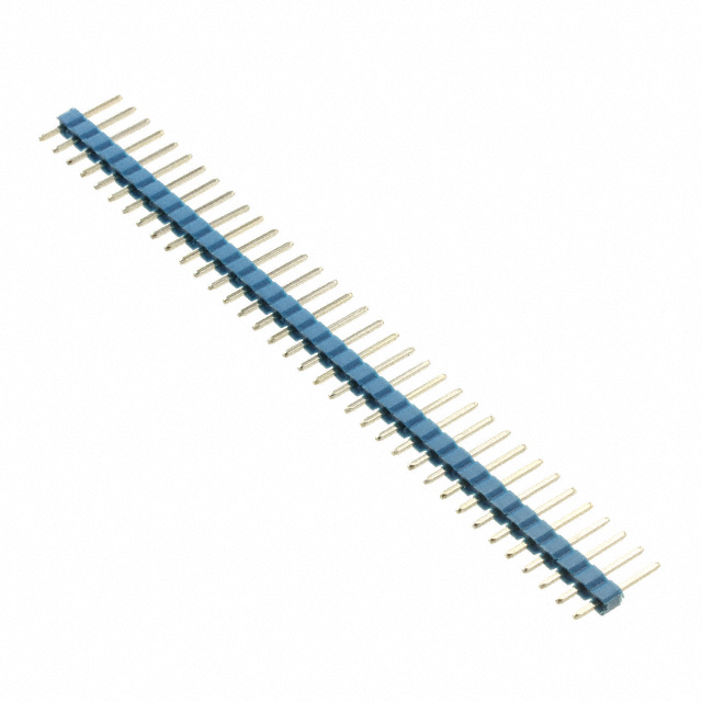
The potentiometer comes with loops instead of pins so it took three individual .1” header pins (the same ones used for the OLED screen and Raspberry Pi Pico) and soldered them to the loops so that it could be used in a breadboard for testing and then soldered into the PCB just like any other device with pins.
I was able to print the case without supports by putting the top half face down to give a smooth top and the bottom half facedown to give a smooth rim to mate with the top half.
Make sure that your USB mini cable fits the printed slot and adjust the model if it doesn’t.
The OLED screen I used is a 0.96" 128x64 OLED with I2C that can operate with 3.3 volts. It can be purchased from various online sellers.
I hope you learned something.
Happy making!