Hands on with the LattePanda
2016-10-18 | By Maker.io Staff
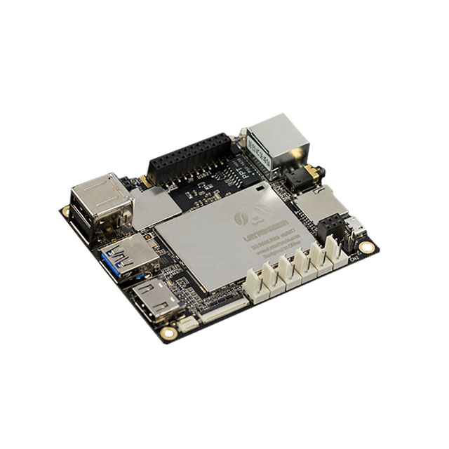
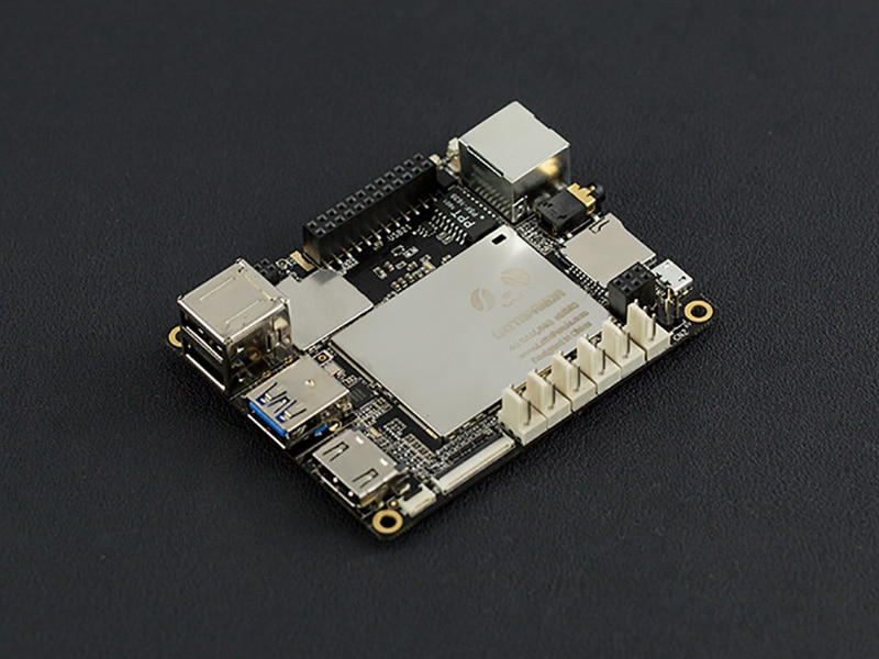
The LattePanda is a full Windows 10 compatible single board computer based on the Intel Cherry Trail CPU. The LattePanda is one of a kind featuring a very powerful hardware setup with the built-in ATmega32u4 microcontroller. I was lucky enough to get my hands on one thanks to DFRobot and LattePanda. They sent me a whole bunch of stuff including the 4GB version of the LattePanda Board, 7” IPS display, 7” Touchscreen overlay, Plywood laser cut case, Starter Sensor kit and lots of peripherals such as a cooling fan, wireless antenna and some heat sinks. This quick guide will give you an insight on how to setup the board as well as using some of the built-in features and the Arduino microcontroller. If you haven’t already done so I would recommend reading up about all the features of the LattePanda on my other blog post at Maker.io, which highlights all the hardware specification in detail.
Powering your Board
One of the best features about the LattePanda is that it can be powered from a MicroUSB power cable. Other boards or similar boards require a DC adapter with a barrel jack to power the board. To power the board, you will need at least a 2A power adapter, anything less will result in performance issues and sudden system reset. The latest official Raspberry Pi power supply should be sufficient with 2.5A or some modern phone chargers usually carry around 2A at least.
1. First step is to plug in your HDMI cable from the LattePanda Board to your HDMI monitor/TV. Plug the Micro USB power adapter into the Micro USB socket on the LattePanda.
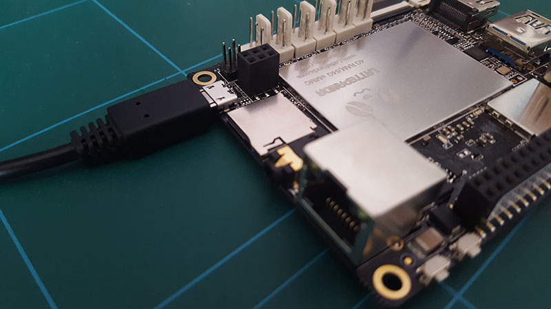
Figure 1: Plug the Micro USB adapter into the Latte Panda
2. When plugged in, you should see the red LED indicator light up underneath the board. This means that the LattePanda board is initializing. After a few seconds you should see the red LED turn off.
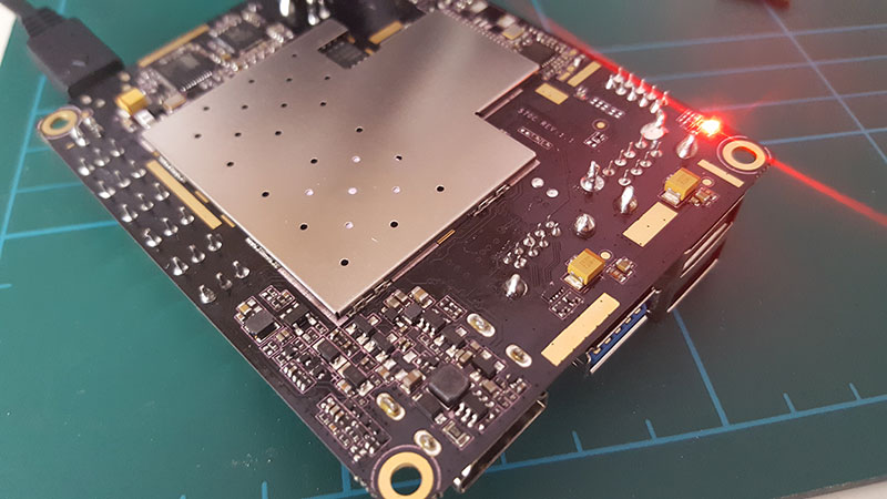
Figure 2: Red LED located underneath the LattePanda Board
3. When the red LED turns off, press and hold the power button for 1 second to turn the LattePanda on. You should see the red LED turn on again.
Connecting WiFi
One of the first things you will most likely do once you have powered up your LattePanda board is to connect to the internet. There are a couple of ways you can do this, one of them is simply connecting an Ethernet cable directly from your router to the board or you can connect to the WiFi using the built-in WiFi on the board. To connect to the WiFi you will need to follow these steps:
1. The first thing you will need to do is install the external WiFi antenna. With my LattePanda I had received two antennas both with the correct u.fl connectors on the end. Locate the U.fl connector, which should be in-between the female breakout headers.
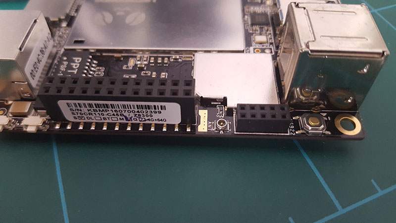
Figure 3: U.fl Connector for the WiFi Antenna
2. Insert the antenna into the board, making sure the connector is firmly connected.
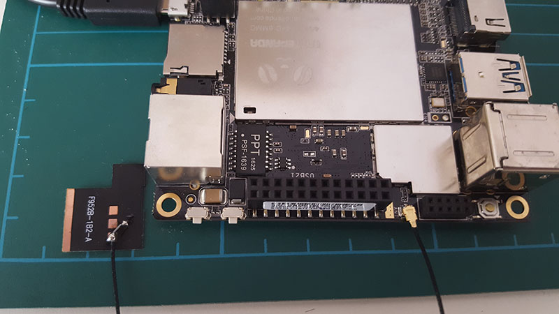
Figure 4: WiFi Antenna Connected to the LattePanda Board
3. In Windows, select the WiFi connection by clicking the WiFi icon in the lower right hand side of the screen. Select your wireless routers SSID and enter the password on the screen. Click Connect to connect to the WiFi.
It's a quite straight forward process and no different than connecting your Laptop/Desktop wireless connection. The only thing you will need to do is properly connect the antenna otherwise you may receive a weak signal or no connection.
Connecting 7” Display and Touchscreen Overlay
The LattePanda 7” IPS screen adds another dimension to your projects. The dev board itself comes with two connectors, one for the 7” screen and another for the touch screen overlay. If you look at other development boards and single board computers most touchscreens require additional circuitry and power making the task complicated. To connect the display and touch overlay follow these simple steps:
1. First, power down your board. If you try to plug the display into the board when it is powered, then you will risk damaging both the board and the display. To be completely sure, unplug the power adapter.
2. Locate the display connector on the LattePanda and carefully lift up the actuator from the horizontal position.
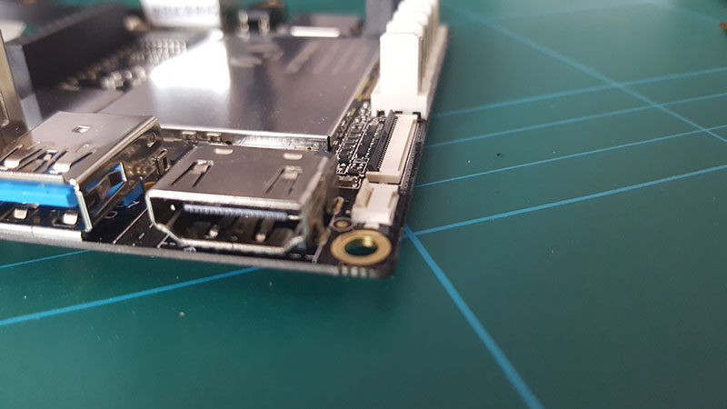
Figure 5: Lift up the actuator on the display connector
3. Insert the displays ribbon cable into the connector making sure the orientation is correct (see figure 6).
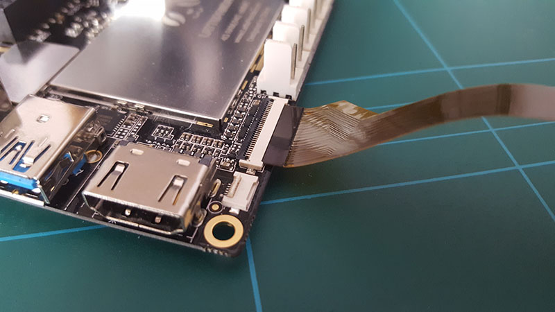
Figure 6: Insert the FPC into the display connector
4. Once inserted you can now close the actuator by pushing it back to the horizontal position, which clamps the FPC cable.
5. Take the Touch screen overlay and carefully peel off the adhesive tape leaving a sticky backing.

Figure 7: Touch Screen Overlay
6. Carefully apply the touch screen on top of the IPS display. Do not worry if the alignment is not accurate as the touchscreen will still work effectively.

Figure 8: Touch Screen Overlay Applied
7. Open the touch screen connector on the LattePanda board and insert the touch screen overlay cable. Close the connector by pushing it into a horizontal position.
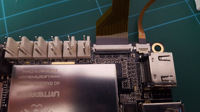
Figure 9: Closed Display Connectors on the LattePanda
Now you can apply the power to the LattePanda and boot up into Windows. The touchscreen function works straight out of the box and requires no additional configuration or calibration. The touch display is by far one of the most impressive I have used on a single board computer with the ability to detect multi-touch and drag and drop with ease.
Everyday Performance
Before I get started with using the Arduino side of the board I wanted to run a number of tests to see how it handles everyday tasks, after all this is a computer and I should be able to use it to do everyday tasks such as watch videos, browse the internet, word processing and some basic level gaming. The first test I did was run a 1080p YouTube video in the web browser, this generally is a good test to its responsive browser performance and also how it can handle multiple tabs. It seemed to play very well without any major lag in the image quality or loading times. I also ran a Netflix movie in the browser at full screen and it handled it pretty well although the frame rate did drop a little. It can also play 4k videos (at a stretch), but I soon came into some problems as it stuttered quite a lot.
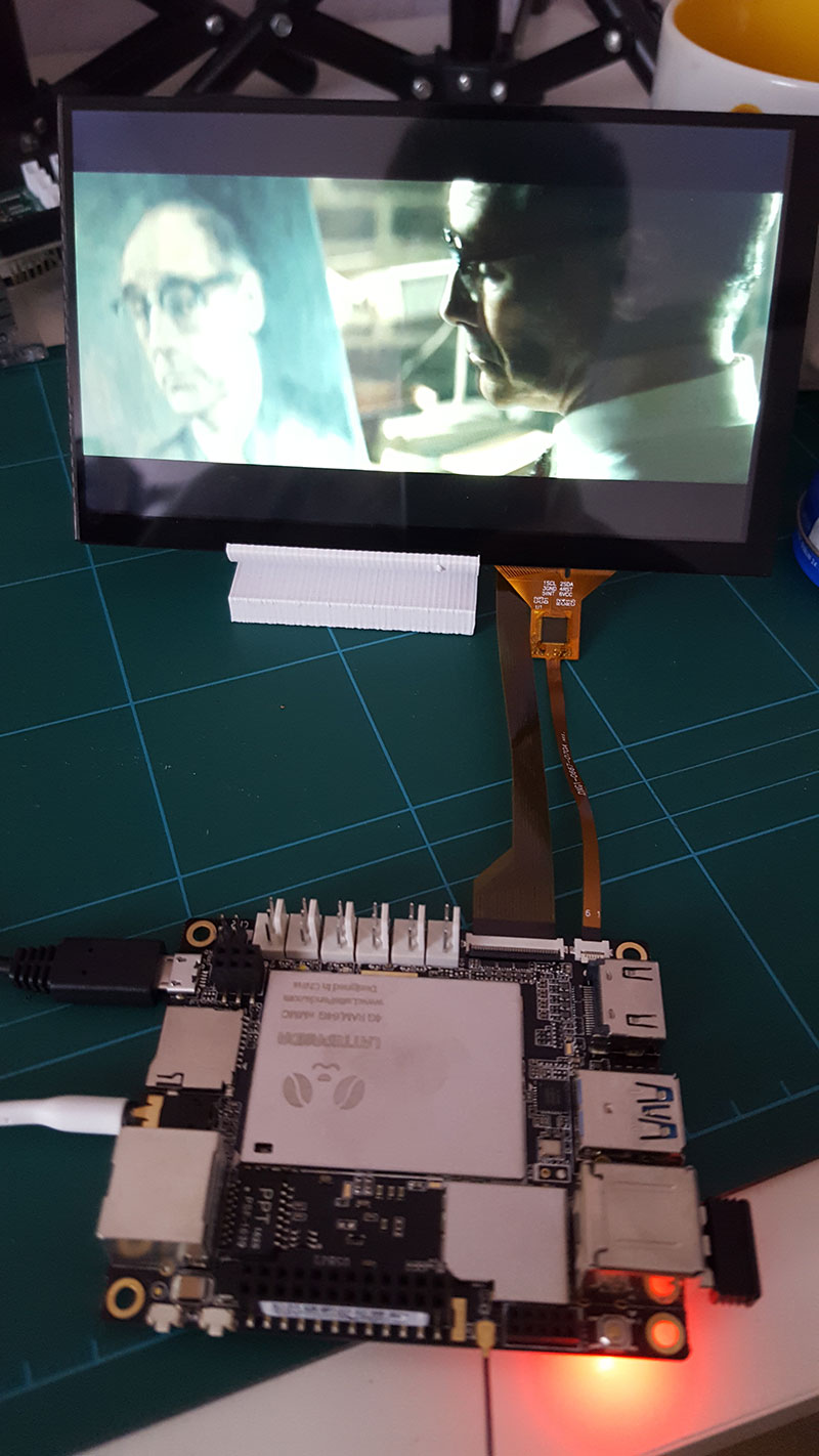
Figure 10: Playing a Netflix video in the web browser
Using Microsoft word processing and other Office tools did not prove a challenge and worked as expected without any hiccups. The LattePanda comes with Intel HD Graphics and so I was interested to see how it performed with some games. So I went about installing Steam, which is a digital gaming service and logged in to my account. The first game I tested was KOTOR and it ran really well on low graphic settings, it was surprisingly very smooth.
Programming the On-Board Arduino Microcontroller
The LattePanda board has a built-in Arduino compatible microcontroller based on the Arduino Leonardo ATmega32u4. In the Windows operating system the Arduino IDE had already been installed and you can see this on the Desktop when you boot up the LattePanda. There have been a few minor issues with some boards that have had corrupt bootloader from the manufacturing process. A good simple test to make sure everything is working on the ATmega32u4 is to load the Blink sketch using the on-board LED connected to digital pin 13. To load a sketch, follow these steps:
1. Open the Arduino IDE software in Windows
2. Open the ‘Blink’ sketch which can be found in File > Examples > 01.Basics > Blink
3. Under Tools > Boards, select the ‘Arduino Leonardo’
4. Under Tools > Serial Port >, select the COM Port 3 which the Arduino is physically connected to.
5. Hit the upload button to upload the sketch to the board.
After a few moments you should see the on-board Blue LED blinking on and off every other second. This is a good indication that everything is working correctly. In the figure below you can see the pinouts for the ATmega32u4 on the LattePanda. There are also a few pinouts connected to the X-Z8300 Core that can also be programmed but not from the Arduino IDE.

Figure 11: LattePanda Pinouts
Each of the 20 Digital pins on the area labelled ‘U2’ can be used as an input or an output. Each digital pin operates at 5V and can output or receive a maximum current of 40mA. Each pin also has a pull-up resistor of 20-50k (Disconnected by default). Some other pins on the ATmega32u4 have some special functions available:
- Analog Inputs: A0 - A5, A6 - A11 (on D4, D6, D8, D9, D10, and D12). The LattePanda has 12 analog inputs, labeled A0 through A11, all of which can also be used as digital I/O. Each pin has a 10 bit resolution (i.e. 1024 different values). By default they measure from ground to 5 volts.
- Serial: D0 (RX) and D1 (TX). Used to receive (RX) and transmit (TX) TTL serial data.
- External Interrupts: D3 (interrupt 0), D2 (interrupt 1), D0 (interrupt 2), D1 (interrupt 3) and D7 (interrupt 4). These pins can be configured to trigger an interrupt on a low value, a rising or falling edge, or a change in value.
- PWM: D3, D5, D6, D9, D10, and D13 provide 8-bit PWM output.
- SPI: D16 (MOSI), D14 (MISO), D15 (SCK).
- LED: D13 There is a built-in LED driven by digital pin 13. When the pin's value is HIGH, the LED is on. When the pin is low, it’s off.
- TWI: D2(SDA), D3(SCL).
- The above information is taken from http://www.lattepanda.com/input-and-output/ from the LATTEPANDA site.
LattePanda Starter Sensor Kit
The LattePanda Sensors Kit by DFRobot is the perfect kit for getting started with programming the physical world. The sensors are part of the DFRobot open-source modular platform for connecting electrical components. You do not require any prior knowledge to electronics or soldering, simply connect the modules using 3-pin cables to the LattePanda board. The sensor kit comes with the following components:
- PIR (Motion) Sensor x1
- Analog Gas Sensor(MQ2) x1
- Analog Flame Sensor x1
- DHT22 Temperature and Humidity Sensor x1
- Analog Ambient Light Sensor x1
- Crash sensor(Left) x1
- Crash sensor(Right) x1
- Digital Push Button (White) x1
- Digital Push Button (Blue) x1
- Analog Rotation Sensor V2 x1
- Digital Blue LED Light Module x1
- Digital RED LED Light Module x1
- Digital White LED Light Module x1
- Relay Module V3.1 (Arduino Compatible) x1
- Gravity Sensor cable x14
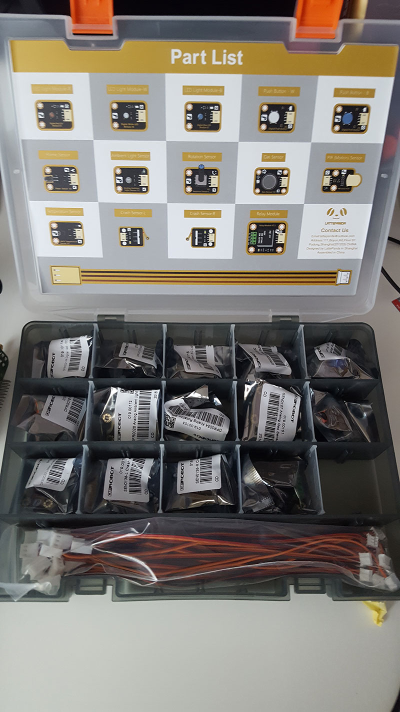
Figure 12: LattePanda Starter Sensor Kit
The LattePanda has six connectors which can interface with the modular sensors as shown in Figure 11. There are a total of 3 analog pins and 3 digital pins.
I created a little project to test out the sensors kit, which uses a PIR motion sensor to switch on a LED. I connected the digital PIR sensor to Digital pin 9 and the LED to Digital pin 10 on the LattePanda.

Figure 13: Digital PIR Sensor and White LED Connected to the LattePanda
The code for the project is below:
byte sensorPin = 9;
byte indicator = 10;

void setup()
{
  pinMode(sensorPin,INPUT);
  pinMode(indicator,OUTPUT);
  Serial.begin(9600);
}

void loop()
{
  byte state = digitalRead(sensorPin);
  digitalWrite(indicator,state);
  if(state == 1)Serial.println("Somebody is in this area!");
  else if(state == 0)Serial.println("No one!");
  delay(500);
}
The project code is taken from the DFRobot Wiki page, where there are great resources and examples for all their modules. There isn’t however, any ability to download the code from GitHub for the Sensor Kit which is a little disappointing. None the less the project worked perfectly, when the PIR motion detector activates it turn on the LED as expected. There are a whole bunch of sensors and actuators available in the kit to produce some really cool projects with the LattePanda.
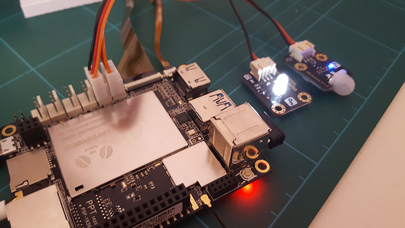
Figure 14: PIR Sensors Activating the White LED Module
Overheating Issues
Yes, there have been some concerns over the heating of the CPU when running some intense applications. There have also been some reports of the CPU being throttled in order to compensate for the overheating to as low as 600MHz. There are however some little hacks that can be done to reduce this issue such as installing some heat sinks in the chips themselves. When looking at the LattePanda board you will notice that there are two metal shields on the top of the board and one underneath. These shields are NOT heatsinks, they are there to protect the board from any physical damage to the IC’s. These shields can be removed to reveal the IC’s and there you can apply a number of heatsinks to the board to reduce the overall heat of the CPU. DFRobot sent me a bunch of heatsinks and also a cooling fan, which fits on the laser cut case.
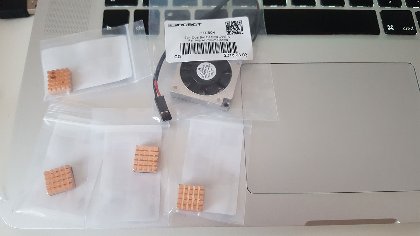
Figure 15: Various Heatsinks and a system Fan for cooling
I ran some tests using RealTemp CPU temperature monitoring. When watching a 1080p movie it uses 2 cores of the CPU at a max of 800MHz and the core temperature was around 70 degrees Celsius on average. Streaming a 4K UHD video in YouTube did initiate an instant system shutdown and I didn’t get to record the CPU temperature.
DFRobot do stock a Heatsink Fan, which when attached to the CPU cover underneath the board does provide effective cooling. Both the Fan and the board will fit inside the Plywood or Acrylic case.
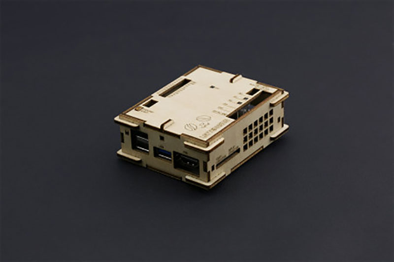
Figure 16: Plywood Case for the LattePanda Board
Summary
Overall this board is amazing and the team at LattePanda have done a fantastic job at putting such a complex board together with all the amazing hardware features. Combined with the accessories such as the touch screen and the sensor kit, everything seamlessly compliments each other and provides quite a unique experience. I haven’t really seen anything else on the market that comes close to the LattePanda with the exception of the UDOO Ultra which will be released 2017. In my next blog I will be taking a look at how to program the ATmega32u4 pin using Visual Studio. If you have any questions relating to the board then please pop them in the comments box below.

Have questions or comments? Continue the conversation on TechForum, DigiKey's online community and technical resource.
Visit TechForum




 中国
中国