


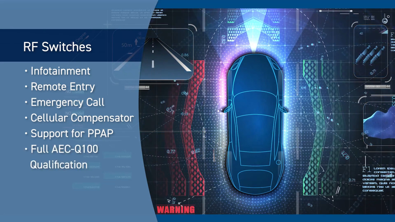
RF Switches Simplify Multi-Antenna Systems
投稿人:电子产品
2012-08-23
Cell phones and other wireless systems that contain multiple radios and multiple antennas often share some of the antennas to reduce system clutter. The latest RF switches give designers the flexibility they need to minimize the number of antennas in a system that today might typically include one or more cellular network radios, a GPS positioning radio, a Wi-Fi interface, a Bluetooth radio, an FM radio, and still other radio systems. The RF switches allow the power amplifier outputs to select the best antenna for the frequency band the system requires, plus the switches can prevent two radios from simultaneously trying to transmit from the same antenna.
RF switches can be implemented in various technologies – mechanical structures such as subminiature relays and micro-electromechanical (MEMS) switches, gallium-arsenide (GaAs) or CMOS FET switches, and even PIN diodes can be used in a switching arrangement. Some of the key specifications for the RF switches include the pass frequency, the voltage standing wave ratio (VSWR), the isolation, the insertion loss, the return loss, the power handling, and the switching speed. Mechanical switches tend to handle the highest power and offer the lowest insertion loss and best isolation, but since they are mechanical, they also have the slowest switching speed, are sensitive to vibration, and can fail due to mechanical wear.
A coaxial relay, for example, can handle high frequencies with minimal insertion losses and high power levels. A PIN diode switch is faster and has infinite life, but can only handle relatively low power and has a higher insertion loss than the mechanical switches. Lastly, FET-based switches have even higher insertion losses but lower video leakage, but are easier to integrate and can handle higher frequencies. FET and PIN diode switches are also more sensitive to overvoltages caused either by electrostatic discharge (ESD) events or by the signal itself. Coaxial relays are sensitive to vibration but relatively unaffected by ESD. Other factors to consider when selecting the best switch for an application include video leakage, ESD immunity, vibration/overstress, size, and repeatability. One issue common to all the switches is the careful circuit board layout required to minimize interference and crosstalk issues. Careful design and proper ground planes are a must to optimize isolation and minimize insertion losses.
Although no one technology offers the best characteristics in all categories, designers can make many tradeoffs by determining the critical specs for their application and then determining which of the remaining characteristics can be eased off to find the switch that best fits their application. There are many suppliers in the RF switch market, some of which include Analog Devices, California Eastern Labs (CEL), Honeywell, Maxim, NXP, New Japan Radio (NJR), Peregrine Semiconductor, and Skyworks Solutions.
Switch configurations follow some of the old mechanical descriptions – single-pole/single-throw (SPST), double-pole/single-throw (DPST), single-pole/double-throw (SPDT), double-pole/double-throw (DPDT), and so on. The number poles/throws needed will be determined by the application, specifically the number of antennas and signal sources that must be switched in the cell phone, satellite, base station, or other RF system.
FET switches, fabricated in either GaAs or CMOS, have higher insertion losses than mechanical switches and also have a limited power-handling capability. The power limitation will typically relegate their use to many of the portable applications that have limited power outputs of a few hundred milliwatts.
Let’s take a look at some of the RF switches available in the market. The Analog Devices ADG901/902 (Figure 1) are wideband SPST switches implemented in CMOS that provide 40 dB of isolation at 1 GHz, an insertion loss of 0.8 dB (also at 1 GHz), and consume less than 1 microamp. Targeted at applications such as wireless communications, general-purpose RF switching, dual-band communications, and digital transceiver front-end switching, the ADG901 is an absorptive (matched) device with 50 Ω terminated shunt legs, while the ADG902 is a reflective switch with no internal shunts (Figure 1). SPDT versions, such as the ADG918/919, provide slightly higher isolation – 43 dB – with the same power consumption and insertion loss as the ADG901/902 switches.

Taking aim at L-band digital cellular systems, cordless phones, Bluetooth, and wireless LAN applications, has developed a broad family of different switch configurations. One device, the UPG2009TB comes in an SPDT configuration and is fabricated using GaAs for low insertion loss – just 0.25 dB at 1 GHz, while providing an isolation level of 28 dB at 2 GHz. The switch can handle an input power of 34 dBm at a frequency of 1 GHz. Able to handle power levels of up to 4 W, the UPG2155TB is aimed at GSM Triple-/Quad-band digital cellular systems and has an insertion loss ranging from 0.35 dB at 1 GHz to 0.45 dB at 2.5 GHz. For large multi-antenna systems, CEL also has an SP10T RF switch that has five ports for WCDMA, three for GSM receive, and two for GSM transmit channels.
Base stations incorporate many antennas to enhance reception and transmission. Devices such as the HRF-SW1030, a SP6T absorptive RF switch from Honeywell, deliver a high-isolation solution – greater than 42 dB at 2 GHz, using a silicon-on-insulator CMOS process. The company claims its SOI CMOS process delivers the performance of GaAs while maintaining the economy and integration capabilities of CMOS.
One of the more complex switch solutions, the MAX12005 from Maxim, is an eight-input, four-output matrix switch targeted at intermediate-frequency (IF) switching in Satellite receivers and L-band signal distribution (Figure 2). The switch is fabricated using a high-performance silicon-germanium (SiGe) process, can operate from 950 MHz to 2.15 GHz, and provides greater than 30 dB of isolation. Included on the chip are gain stages to compensate for splitter insertion loses and four DiSEqC 2.0 decoders with an integrated oscillator and four alternate tone/voltage decoders. Two of the chips can also be cascaded to expand the number of input channels to 16.

A wide selection of SPDT GaAs switches is also available from NJR. Switches such as the NJG1506R are targeted at cellular handset receive channels have insertion losses of about 0.3 dB and isolation levels of about 27 dB. Switches in DPDT and in SP4T configurations are also available, offering higher isolation levels up to 42 dB and a low insertion loss of 0.3 dB. The SP4T switch is aimed at antenna switching in dual-mode cell phones such as required for GSM/DCS1800 applications (Figure 3).

A simple SPDT switch, the SA630 is one example of the switches offered by NXP. Fabricated using a BiCMOS process, the switch is targeted at applications such as a digital RF transceiver front end, and would typically replace a duplexer in cordless phones. The chip could also be used to generate amplitude-shift-keying (ASK), on-off keying (OOK), or frequency-shift-keying (FSK) signals for digital RF communications systems.
The companies that offer some of the broadest switch offerings, Peregrine Semiconductor, RFMD and Skyworks Solutions, employ very different technologies to implement their solutions. Peregrine, for starters, uses its proprietary UltraCMOS process, which is a variation of silicon-on-insulator technology on a Sapphire substrate. The switches have input-to-output isolation levels of greater than 35 dB at 1 GHz and an insertion loss of just 0.3 dB. One device, the PE42551 has a frequency span of 9 kHz to 6 GHz and is designed to support requirements in the test equipment and ATE systems market. The chip manages to maintain an isolation of 21 dB at 6 GHz and an insertion loss of 0.90 dB, also at 6 GHz.
Designers at RFMD leverage a GaAs MESFET processor to offer a family of transmit/receive switches that have an insertion loss of 1 dB at 900 MHz and handle power levels of up to 20 dBm. Two offerings from RFMD are targeted at broadband communications, test instrumentation, fiber-optic systems and military/aerospace applications – the RFSW2042 and 2045 leverage a GaAs p-channel high-electron-mobility transistor technology (pHEMT) to offer a DC to 15 GHz SP3T switch and a DC to 16 GHz SP4T switch, respectively. For the RFSW2042, the insertion loss is 2.1 dB at 15 GHz and the isolation is 37 dB, while the RFSW2045 has an insertion loss of 2.4 dB at 16 GHz, and an isolation of 38 dB.
Also leveraging the GaAs p-HEMT technology to fabricate its RF switches, Skyworks offers many SPDT variations and some more complex switches, including an SP5T switch, the AS195-306, which offers five symmetric RF paths and an insertion loss of about 0.6 dB at 1 GHz. The company also has a high-power PIN diode SPDT switch targeted for use in SCDMA, WiMAX, and LTE base stations. The chip can handle a continuous power level of 50 W and a peak power of 200 W (Figure 4).

To sum up, multiple antenna systems are used to replace traditional single antenna circuitry in radio transceiver systems in order to improve transmission capability and reliability. To avoid the use of multiple RF chains associated with these multiple antennas, an RF switch is essential. The broad range of available RF switch configurations and performance capabilities gives designers plenty of options from which they can select the best switch to meet their system requirements. The switches can handle power requirements ranging from a few milliwatts to over 50 W of continuous power, thus allowing designers to develop products ranging from cell phones to base stations to satellite communications systems. This article has explored example RF switch parts from Analog Devices, California Eastern Labs (CEL), Honeywell, Maxim, NXP, New Japan Radio (NJR), Peregrine, RFMD, and Skyworks. For more information on these products, use the links provided to access product information pages on the DigiKey website.
免责声明:各个作者和/或论坛参与者在本网站发表的观点、看法和意见不代表 DigiKey 的观点、看法和意见,也不代表 DigiKey 官方政策。


 中国
中国