How to Protect Circuits From High-Temperature Overload and Fault Currents
投稿人:DigiKey 北美编辑
2023-06-14
Circuit protection is vital in order to safeguard electrical machinery and equipment from hazardous current increases. There are two classes of hazardous situations; one is where the overcurrent potentially overloads the powered equipment, and the other is where there is a short circuit or line-to-ground fault, causing a rapid and damaging increase in current.
A popular, mature, and proven technology for the protection of valuable assets is the electromechanical circuit breaker. This type of device covers a wide range of applications but is less useful for things like electric motors which are subject to inrush current on start-up. A better option in these situations is to use thermal magnetic circuit breakers, as they provide a slight delay before tripping.
Still, there are situations where even thermal magnetic circuit breakers are unsuitable. Examples include applications with extreme swings in temperature or applications such as generator rooms where temperatures are constantly elevated. The answer for combined overload/fault current protection in such applications is the hydraulic magnetic circuit breaker. This device offers the advantages of thermal magnetic circuit breakers—without the drawback of being affected by large ambient temperature swings.
This article describes the function and characteristics of thermal and hydraulic magnetic circuit breakers, and why the latter suits applications with widely varying temperatures. The article then describes the various types of hydraulic magnetic circuit breakers using real-world examples from Sensata Technologies, including a design example.
Magnetic and thermal circuit breakers
The protection mechanism of a magnetic circuit breaker comprises a solenoid and a metal lever. Above a predefined current threshold, the solenoid’s magnetic field is sufficient to attract the circuit breaker’s lever and open the circuit. The device is the simplest and least expensive type of electromagnetic circuit breaker and is suitable for many situations where straightforward overload and line-to-ground fault protection is needed. Once tripped, the circuit breaker is reset by manually flipping its lever.
The main downside is that the magnetic circuit breaker will trip immediately—even if the excess current lasts for only a very short time. This is a disadvantage if the device is protecting a large electric motor, for example. Such motors are prone to large inrush currents as they start up. The inrush current typically exceeds the overload current but lasts for a short time so it doesn’t cause motor damage. However, such currents do trip magnetic circuit breakers.
The thermal circuit breaker offers an alternative. This device is based on a bimetallic strip (or “thermal element”). The most common thermal element is a sandwich of two or three different metals. The low-expansion side is typically invar, a nickel steel alloy that has a low coefficient of thermal expansion. The center element is typically made of copper, for low resistivity, or nickel, for high resistivity, depending upon the application. Metals used in the high-expansion side vary considerably. The size of the thermal element, configuration, physical shape, and electrical resistivity determine the current capacity of the circuit breaker.
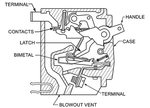
For overload situations, where the peak current only causes damage if applied for longer periods, the thermal element provides good protection. The relatively high current heats the thermal element due to its resistance and causes the contacts to open. There is a sufficient delay in the thermal element’s operation such that the circuit breaker doesn’t trip for transient overloads like motor inrush currents. The trip time is generally inversely proportional to the overload current (Figure 1).
 Figure 1: This cross-section of a thermal circuit breaker shows the thermal element which trips the device when heated by overload currents. The resistive heating generates a time delay that prevents tripping due to transients such as electric motor inrush currents. (Image source: Sensata)
Thermal magnetic circuit breakers combine both thermal and magnetic elements into a single device. Overload currents don’t generate a strong enough magnetic field in the solenoid to operate the trip lever but do heat the thermal element so that it eventually trips. On the other hand, fault currents immediately generate a high magnetic field in the solenoid, overriding the thermal element and immediately opening the circuit.
One drawback to thermal magnetic circuit breakers shows up in applications where equipment is particularly sensitive. In such instances, overload currents are typically lower than 5 amperes (A), and don’t generate enough heat to activate the bimetallic strip. This can be overcome by adding a heating coil to the strip to prewarm it and increase its sensitivity—with the downside of added complexity.
A critical drawback of both thermal and thermal magnetic circuit breakers is their sensitivity to ambient temperature changes. For example, a 10 A circuit breaker may trip at currents as low as 7 A in high temperature environments, or at currents as high as 13 A in a colder environment. Manufacturers assist by producing derating tables to indicate actual trip currents in hot or cold environments, but there are compromises to be made.
For example, engineers often overspecify thermal circuit breakers destined for use in hot environments to combat nuisance tripping, thereby increasing the possibility of the equipment being exposed to high currents. Similarly, for use in colder environments, the circuit breaker can be derated to ensure it trips at a lower current, which can increase the likelihood of unnecessary tripping (Table 1).
|
Table 1: Manufacturer’s derating table indicating actual trip currents for thermal circuit breakers at specified temperatures. Note that the rated current is specified at +30°C. Trip currents are higher than the rating at colder temperatures and lower at warmer temperatures. (Image source: Sensata)
Overspecifying or derating is a satisfactory solution in environments where the temperature is relatively consistent—either hot or cold—but is less than optimum for areas with wide temperature swings. A derated circuit breaker designed for a warm environment could fail to protect equipment when the temperature drops.
How to address wide temperature swings
Hydraulic magnetic circuit breakers eliminate the thermal element and thus remove any problems associated with temperature variations. The devices are consistent in rating and performance across the industrial temperature range of -40°C to +85°C.
As the name suggests, the devices use a magnetic element from a simple magnetic circuit breaker, but here the solenoid core is held by a spring in a tube, and movement is damped by hydraulic (silicone) fluid. If the current flowing through the unit remains at—or below—the rated current, the mechanism will not trip. If an overload current increases to between 100% and 125% of the rated current, the magnetic flux generated in the coil is sufficient to move the core against the spring to trip the device.
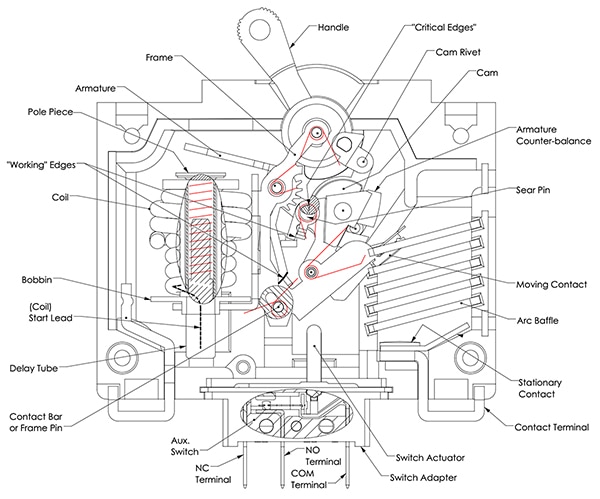
In the case of overload currents, generating relatively weak magnetic fields, the spring and damping fluid slow down the movement of the core enough such that it doesn’t trip for transient overloads such as motor inrush currents. Different time-delay curves can be obtained by using fluids of different viscosities. However, for genuine fault currents, the solenoid magnetic field is strong enough to instantly overcome the damping and break the circuit (Figure 2).
 Figure 2: This cross-section of a hydraulic magnetic circuit breaker shows the magnetic element and inner damped core (at left) that trips the device when overload or fault currents generate a sufficiently large magnetic field. The damping fluid in the core tube creates a time delay. Trip operation is largely unaffected by temperature. (Image source: Sensata)
Figure 3 compares the impact of temperature extremes on the time-delay curves for a thermal circuit breaker and a hydraulic magnetic circuit breaker (from Sensata’s Airpax line). The graphs define curves for the 100% and 125% rating currents for both product types.
 Figure 3: The impact of large temperature variations on the delay of thermal circuit breakers is much greater than it is on hydraulic magnetic devices. (Image source: Sensata)
For the Airpax product, a temperature swing of +125°C has little effect on the delay curve. For example, at +85°C and for an overload of 250% of the rated current, the trip delay is between 0.013 and 0.2 seconds (s). At -40°C the delay for the same current is between 0.018 and 1 s. For higher currents, the differences between the delay curves at these temperature extremes are even less.
For the thermal circuit breaker, the impact of temperature is much greater. Furthermore, at the high temperature, the minimum trip level is well below the 100% rated current, and for the low temperature, it is well above the 100% rated current. This is due to the temperature effects on the thermal element discussed above. At +85°C, and for an overload of 250% of the rated current, the trip delay is between 0.8 and 3.0 s. At -40°C, the delay is between 40 and 600 s. For higher currents, the differences between the delay curves are less extreme, but still significant.
Design considerations for hydraulic magnetic circuit breakers
Apart from its tolerance to wide temperature fluctuations, a key reason for selecting a hydraulic magnetic circuit breaker over other types is to ensure the device doesn’t keep tripping due to the inrush current to electric motors, transformers, or large capacitors. Such tripping is disruptive to machinery operation.
Before even considering the impact of inrush currents on circuit breaker selection, the engineer needs to work out a rating for the circuit breaker for standard overload and fault protection. A rule-of-thumb is to choose a circuit breaker rating equal to 100% of the continuous load demanded by the connected circuit. However, it is important to consider the magnitude and duration of any surges that occur during normal equipment operation.
The engineer also needs to specify the maximum operating voltage—typically 80, 125, 240, 250, or 277 volts—and the operating frequency—typically direct current (DC), or 50/60 or 400 Hertz (Hz) alternating current (AC).
A common mistake is to waste money by overspecifying the circuit breaker’s rating to build in a margin of safety and prevent nuisance tripping. However, unlike a fuse, the rating of a circuit breaker is the maximum current that can be continuously carried, not the current at which it will trip. A 20 A circuit breaker will easily accommodate a temporary surge of 25 A. However, if surge currents typically last longer than 60 s, it is good design practice to specify a circuit breaker rated at 100% of the surge current rather than the normal continuous current.
The other key performance characteristic is to decide on the appropriate delay curve for the circuit breaker. To do this, the engineer needs to know how large and how persistent the inrush current will be. One way to check the inrush current peak and duration is to start up the machinery while the circuit is monitored via an oscilloscope. Repeating the measurement several times will allow the average peak and inrush current to be determined. The designer could also consult the equipment manufacturer’s datasheet. However, this is less precise because of local factors such as line loss and the impact of other components.
Selecting a hydraulic magnetic circuit breaker for an electric motor application
Once designers have determined the maximum operating voltage, operational frequency, continuous current, surge current and duration, and inrush current and duration, they can select an appropriate hydraulic magnetic circuit breaker.
Sensata’s Airpax IEG series is available in a wide variety of configurations, including units with auxiliary switch, shunt, and relay, with a choice of delays and ratings, operating voltages between 80 and 250 volts, and either DC, 50/60 or 400 Hz versions. Handles come in seven different colors, and international markings are standard.
For example, the IEG1-1REC5-69-.100-21-V is rated at 100 milliamps (mA). In the mid-range is the 20 A IEG11-1-61-20.0-01-V (Figure 4), and at the high end is the 100 A IELK1-1-72-100.-01.
 Figure 4: Sensata’s IEG11-1-61-20.0-01-V hydraulic magnetic circuit breaker is rated at 20 A and is available for several supply inputs, including 250 volts, 50/60 Hz. (Image source: Sensata)
Consider an example of a hydraulic magnetic circuit breaker protecting a large AC electric motor. The supply voltage is 250 volts AC at 50/60 Hz, and when normally running the motor current is a continuous 20 A. There are temporary current surges—as other equipment connected to the power circuit starts and stops—of up to 25 A for between 20 and 45 s. At start-up, the inrush current peaks at 100 A (500% of continuous current) for 0.6 s, and drops to the continuous operation level in just under 1 s.
In this example, the surge current occurs for less than 45 s, so it’s safe for the designer to select the rating based solely on the continuous current of 20 A. The Sensata IEG11-1-61-20.0-01-V has a 20 A rating and is available in a 250-volt, 50/60 Hz version, so it would be a good choice for this application.
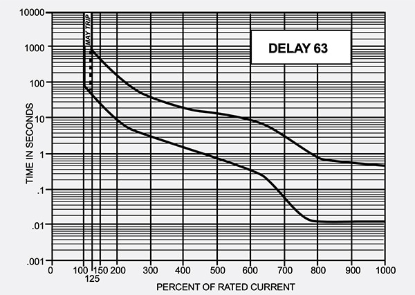
Sensata provides delay charts for this model on the datasheet. For example, Delays 42, 52, and 62 are suitable for use with 50/60 Hz devices and are long enough to cater to the inrush currents of certain types of motors and most transformer and capacitor loads. Delays 43, 53, and 63 feature longer delays for special motor applications. Figure 5 shows Delay 63, and from the curve, at the peak surge current of 100 A (500%), the device will trip between 0.8 and 15 s. This enables it to cope with the example motor’s inrush current—which peaks in 0.6 s and rapidly tails off—without tripping.
 Figure 5: Sensata’s hydraulic magnetic circuit breaker Delay 63 features a longer delay for special motor operations. Even at 650% of the rated current, the trip time is no less than 0.2 s. (Image source: Sensata)
It is good practice to mount hydraulic magnetic circuit breakers vertically; otherwise, the core can drag in the tube and extend the trip time.
Conclusion
Electromagnetic circuit breakers are a robust option for machinery circuit protection, though thermal and thermal magnetic devices are often a better option as their built-in time delay prevents repetitive nuisance tripping. However, when equipment is subject to a wide variation in temperature, hydraulic magnetic circuit breakers have the time delay necessary to protect equipment subject to inrush currents—while keeping that delay consistent across a wide temperature range.

免责声明:各个作者和/或论坛参与者在本网站发表的观点、看法和意见不代表 DigiKey 的观点、看法和意见,也不代表 DigiKey 官方政策。


