Digital Isolation Devices Find Pervasive Role in Energy Harvesting Applications
投稿人:电子产品
2015-08-26
Isolation plays a pivotal role in energy harvesting systems, providing protection from high voltages not only to human operators but also to sensitive electronic circuits within these systems. Ensuring suitable isolation in designs requires matching application characteristics with isolation technology. For engineers, building a properly isolated system has become simpler thanks to an array of isolation components available from vendors including Analog Devices, Avago Technologies, Infineon Technologies, Maxim Integrated, NVE, Silicon Labs, Texas Instruments, and Toshiba Semiconductor.
In high-voltage applications such as solar-energy harvesting or battery-stack management, galvanic isolation is essential for protecting users and systems from hazardous voltage levels. Isolation is no less important in low-voltage applications such as ambient-powered wireless sensors where noise, transient signals, common-mode voltages, and other factors can degrade measurement accuracy or even damage sensitive components.
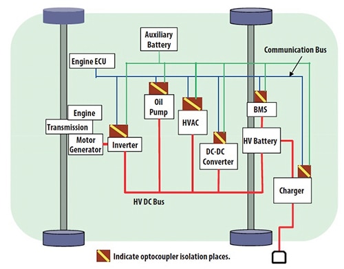
In any application, isolation devices allow systems to pass signals between different voltage domains while preventing current from passing between them. For example, isolators are used throughout electric vehicles, providing a barrier between the low-voltage system used by digital components and the high-voltage system used to drive motors, recharge primary batteries, and supply system power (Figure 1).

Figure 1: Isolation plays a pivotal role in separating different voltage domains while allowing signals to pass freely between them. Electric vehicles, for example, rely on isolators placed throughout the system to separate the high-voltage drive bus from the low-voltage signaling bus. (Courtesy of Avago Technologies)
Although isolation can occur in both analog and digital domains, the use of digital isolators can provide greater flexibility in design—both in choice of components and circuit optimization. For example, in sensor signal chains, the use of digital isolation allows designers to shorten the signal chain between sensor and ADC to enhance analog performance of the chain itself. Furthermore, this approach avoids accuracy problems that can arise if analog isolation components introduce errors in gain, nonlinearity, and offset before the signal reaches the ADC.
Digital isolation technologies
Digital isolators typically rely on optical, capacitive, or magnetic-coupling technologies to transmit bit streams between different voltage domains. Considering their critical role in product safety, basic performance parameters are strictly regulated by national and international standards. Optical isolators have been in use for some time and are governed by the IEC 60747 and UL 1577 standards. Other standards such as VDE 0884-10 and IEC 60747-5-5 specify additional performance characteristics associated with capacitive and magnetic technologies. Consequently, manufacturers using these different technologies deliver components offering similar performance characteristics, such as operating voltage, isolation voltage, and common-mode transient immunity (CMTI). In contrast, these technologies can offer significant differences in power requirements, data transmission rate, and electric- or magnetic-field immunity.
An optoelectronic isolator at a minimum comprises an LED and a photodetector, typically separated by an air gap that provides a physical-isolation barrier. The LED transmits signals as a variation in light intensity across this barrier to the photodetector, which converts the transmitted light back to the original signal. Manufacturers build on this basic design with additional circuitry to enhance performance and reliability. For example, the Avago Technologies HCPL-7723 optoisolator combines LED and photodetector with a high-speed transimpedance amplifier and a voltage comparator with an output driver (Figure 2a), while the Avago ACSL-6210 offers bi-directional channels (Figure 2b).

Figure 2: Available optoisolators extend the basic LED-photodetector circuit with amplifiers and comparators (A) or with bidirectional channels (B). (Courtesy of Avago Technologies)
One of the most commonly used methods for isolation, optical isolation offers immunity to electrical and magnetic noise. Consequently, this approach is particularly effective in industrial and automotive applications, where strong electric or magnetic fields could be present.
On the other hand, LED-power-dissipation characteristics can translate to higher power requirements. Furthermore, continued use can result in LED wear and possible failure after years of use. As a result, designers will often look to other isolation technologies for solar-energy harvesting systems where 20-year endurance is typically specified. Finally, the use of LEDs and their restricted switching speed translates to lower transmission speeds than possible with other isolation technologies. Nevertheless, designers can find high-speed optoisolators such as the just-mentioned Avago HCPL-7723 and Toshiba Semiconductor TLP117. Both of these devices provide 50 MBd transmission rate, 22 ns (max) propagation delay, 3750 Vrms isolation voltage, and 10 kV/µs CMTI.
Electromagnetic coupling
For long-life applications or those requiring the highest possible date rates, designers can turn to devices based on capacitive or magnetic isolation. Both types of devices can achieve transmission rates up to 150 Mbps with correspondingly short propagation delays. For example, capacitive-based isolators such as the Maxim Integrated MAX14934, Silicon Labs SI8422, and Texas Instruments ISO7641 isolator achieve 150 Mbps data rates with propagation delays of 7.5 ns, 11 ns, and 10.5 ns, respectively.
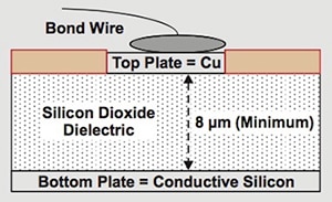
Capacitive isolators rely on an isolation barrier formed by two capacitors, each with a copper top plate and a conductive-silicon bottom plate on each side of a silicon-dioxide dielectric (Figure 3). The input side of the isolator connects by bond wires to the top plate of the isolation capacitor, while the output side connects to the bottom plate. Input signals result in a change in the electric field across the capacitor, resulting in a proportional change in charge detected by the output side, which reconstructs the original signal accordingly.

Figure 3: Capacitive isolators transfer signals as changes in electric field across the plates of a capacitor separated by the dielectric isolation barrier. (Courtesy of Texas Instruments)
For all practical purposes, capacitive isolators are immune to magnetic fields. On the other hand, their use of electric fields for signal transmission means they are susceptible to external electric fields—causing possible concerns for applications operating near high-voltage lines, for example. Still, manufacturers use closely spaced differential inputs to the capacitor plate in these devices to significantly mitigate the effect of external electric fields. To further enhance electromagnetic immunity, devices such as the SI8422 in the Silicon Labs ISOpro family use an RF transmitter and receiver to pass the signal across the capacitive isolation barrier. The receiver contains a demodulator that decodes the input state according to its RF energy content to reconstruct the input signal at the device’s output pin.
Conversely, magnetic-coupling isolators such as devices in the Analog Devices iCoupler family and Infineon Technologies ISOFACE family are effectively immune to electric fields. Of course, with their use of a magnetic field for signaling, these types of isolators can be susceptible to interference from external magnetic fields. As with capacitive isolators, inductive-coupling devices are layered structures. Where capacitive isolators use a pair of capacitor plates separated by dielectric, inductive-coupling devices use a pair of coils separated a layer of insulation to create the isolation barrier between the device’s input and output pins. Input signals result in variations in current flowing through the input-side coil, inducing a proportional current in the coil on the output side of the isolation barrier. The device’s output stage detects these changes in current in the output-side coil and reconstructs the original signal.
Giant Magneto resistor (GMR) isolators are similarly based on magnetic coupling but rely on a very large, or “giant”, variation in resistance of thin-film materials with application of a magnetic field across the insulation barrier. This very large change in resistance in the GMR resistor structure on the output side of the device results in a large output signal that can offer enhanced sensitivity and accuracy. GMR technologies enable very fast switching speeds, allowing devices such as the Avago Technologies HCPL-090J and NVE Sloop family devices such as the NVE IL712 to achieve data rates of 100 MBd and 150 Mbps and propagation delay of 15 ns and 10 ns, respectively. Furthermore, the stability of the materials used in GMR isolators enables very long product life. For example, NVE quotes a 44,000 year barrier life for its Sloop family devices.
Conclusion
Galvanic isolation is critical for safety in high-voltage applications and reliability in low-voltage applications. For designers, digital isolator ICs offer a simple approach for ensuring proper isolation in any circuit. To meet specific demands for transmission speed, electromagnetic immunity, and other operating characteristics, engineers can find a wide range of suitable digital isolator ICs based on optical, capacitive, or magnetic coupling technologies.
For more information on the parts discussed in this article, use the links provided to access product pages on the DigiKey website.
免责声明:各个作者和/或论坛参与者在本网站发表的观点、看法和意见不代表 DigiKey 的观点、看法和意见,也不代表 DigiKey 官方政策。


