Using Network Power for Building Automation Devices
投稿人:DigiKey 欧洲编辑
2015-11-10
Power over Ethernet (PoE) provides a convenient way to deliver both power and data connectivity to remote equipment using a single cable. This makes it a power-delivery solution that is highly suited to building automation systems and one that promises to deal with many of the problems of existing networks that are often based on a mixture of proprietary protocols and connections.
Many buildings are already provided with large-scale data infrastructure based on the Category-5 cable required by 10BaseT and 100BaseT Ethernet. This reduces the amount of new cabling needed to connect a wide variety of building automation devices, such as IP video cameras and RFID readers as well as wireless access points that can provide extended connectivity to wireless, battery-powered sensor nodes.
PoE takes advantage of the fact that a Cat5 cable contains four pairs of wires. Although later, higher-speed Ethernet standards transmit data on all four pairs, only two pairs are used for sending bits under the 10Base-T and 100Base-T standards.
The most recent version of the IEEE 802.3af PoE standard makes it possible to provide up to 25 W of power to a remote device, with some vendors going beyond some of the restrictions in the standard to extend this to just over 50 W or to improve overall efficiency. The lower aggregate resistance of doubling the number of pairs reduces transmission losses. The IEEE has formed a task force to develop a standard for four-pair PoE that would allow for increased power delivery and improved efficiency. The task force expects the standard to be ready in 2017.

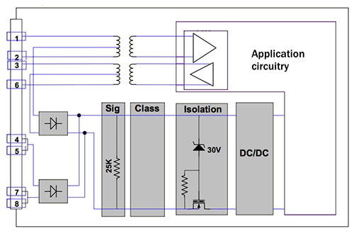
Figure 1: Conceptual view of a system powered by an IEEE 802.3af connection.
Limits are set in the standard to ensure that the self-heating caused by wire resistance within a bundle of cables is not excessive. Cat5 cable uses 24 AWG conductors, which traditionally have been deemed safe to carry up to 360 mA at 50 V, with a high margin to allow for differences in resistance of various cables. If half of the conductors are used for carrying power, this allows up to 36 W to be supplied. The voltage drop from a cable run of 100 m – the rated maximum length for twisted-pair Ethernet – means that the device at the far end would, in principle, receive just under 32 W from the two pairs. The move to Cat6 cabling provides reduced resistance, which could support the higher power delivery of future four-pair PoE standards more readily.
The power itself may be delivered by a PoE switch that also handles data, or it may be supplied further along the cable run by a midspan device. This midspan injector could be used to provide energy from solar panels to individual devices, such as IP cameras, that are installed outdoors.
Although there are two unused pairs that could be dedicated to power over 10Base-T or 100Base-T Ethernet connections, the standard allows for the data-carrying pairs to be used instead. Mode A uses the data pair; Mode B delivers power over the spare pairs.
Power supply over data pairs is made possible by Ethernet’s use of differential signaling to send bits, extending support for PoE to 1000Base-T devices. A transformer-based connection ensures that the high current from the power supply does not affect the data circuitry.
Mode A uses pins 1 and 2 to carry the supply rails with pins 3 and 6 used for the return. Mode A additionally supports two configurations to allow the polarities of the connections to be swapped. This allows power to be supplied using crossover or patch cables and in systems that use auto-detection of cable type. In Mode B pins 4 and 5 provide the DC rail with 7 and 8 used for the return.
The power-sourcing equipment (PSE) determines which of the two options it should employ to deliver energy to the powered device (PD). However, a compliant PD must support both Mode A and B. It indicates that it can receive power in either mode by having a 25 kΩ resistor placed between the data pairs.
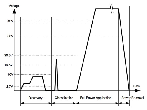
When a PD is connected to a PoE system it transitions through several operating modes in sequence including detection, classification, turn-on and normal DC operation. Each operating mode uses a specific voltage range, all of which are supplied from the PSE. During detection, the PSE probes for the signature resistor. If the PSE finds that the resistance between those pairs is too high, it will refuse to supply power to the device. Classification is an optional mode that the PSE uses to determine the power requirements of each attached PD, and so allocate the most appropriate current levels. This again uses a resistor. Its value determines which of four current classes is to be used, placed across pins 4 and 7.

Figure 2: The setup and operational phases of PoE and their associated voltages.
Because of the range of options available under PoE and the need for PDs to follow the protocol in order to be able to draw the power they need, a dedicated DC/DC converter or a front-end device for an existing power converter is needed. Front-end devices often extend the functionality of PoE to support other power options. One example is the LM5073 made by Texas Instruments. The LM5073 provides the flexibility for the PD to accept power from unregulated auxiliary sources such as AC adapters and solar cells. The provision of a 100 V MOSFET designed for hot-swap support and a programmable DC current limiter makes it possible to handle twice the power level of IEEE 802.3af-compliant devices. Further, a 100 V maximum voltage rating simplifies selection of the transient voltage suppressor that protects the PD from network transients.
To support integration, the LM5073 incorporates the PD signature resistor and the ability to program the classification resistance using a current source. Support for inrush current limits, a programmable undervoltage lockout (UVLO) and thermal shutdown further simplify PD implementation.
To use a device such as the LM5073, the system’s DC/DC converter needs to have a soft-start feature so that it can control input current during startup. The soft-start process reduces the surge of inrush current and eliminates any tendency of the output voltage to overshoot during startup. The converter needs to be started slowly enough such that the input current does not exceed the PD interface’s hot-swap MOSFET DC current limit or the current limit of the PSE. Otherwise the PD will not start correctly.
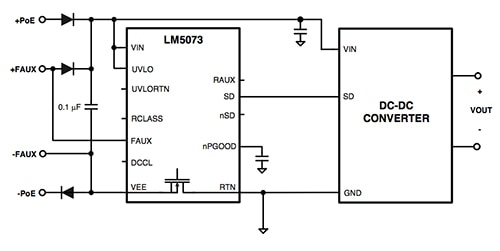
The LM5073 accepts two different auxiliary power configurations. The front auxiliary (FAUX) mode allows for the auxiliary source to be used in parallel with the Ethernet supply through an OR-diode configuration. The second configuration is the rear auxiliary (RAUX) option in which the auxiliary power bypasses the PoE interface altogether and is connected directly to the input of the DC/DC converter through a diode. The FAUX option is desirable if the auxiliary power voltage is similar to the PoE input voltage. However, when the auxiliary supply voltage is much lower than the PoE input voltage, the RAUX option is more suitable as the current from the auxiliary supply is not limited by the current limit of the hot-swap MOSFET.

Figure 3: The TI LM5073 is designed to act as a PoE front-end for DC/DC converters.
Another option is the LTC4267 from Linear Technology. It is a PoE PD interface with its own integrated switching regulator to provide a complete power solution for systems that need up to 1.5 A current at 3.3 V. The LTC4267 integrates the required 25 kΩ signature resistor, a current source for the classification phase, thermal overload protection and undervoltage lockout that employs a 100 V, 400 mA-capable MOSFET to provide a high degree of protection to the back-end electronics with comparatively inexpensive voltage suppressors.
The current mode switching regulator on the LTC4267 is designed for driving a 6 V rated N-channel MOSFET and features programmable slope compensation, soft-start and constant frequency operation. The device includes an onboard error amplifier and voltage reference allowing use in both isolated and non-isolated configurations.
The front-end functions are also available in devices such as the LTC4265, which is designed to provide PD functions for an existing switching regulator. In this case, a 100 V, 100 mA MOSFET is used to isolate the Ethernet-borne supply from the DC/DC converter during the detection and classification phases.
To support situations where it is too expensive to upgrade existing Ethernet switches to be PSE capable or used in areas where only a few PoE devices need to be deployed, single-port injectors are available. One example is the Phihong POE36U-1AT, which offers compatibility with 1000Base-T connections. Powered from a mains supply operating between 90 V and 264 V, the unit can provide up to 33.6 W to the PD.
Thanks to front-end devices and the availability of midspan injectors, adding PoE capability to building automation devices is now relatively easy to accomplish. By building support for Ethernet connectivity, system designers can take advantage of the wide support for the protocol and be assured that energy delivery can be achieved without dedicated power cabling and inputs, although these may be used to provide additional flexibility.

免责声明:各个作者和/或论坛参与者在本网站发表的观点、看法和意见不代表 DigiKey 的观点、看法和意见,也不代表 DigiKey 官方政策。


