Tips and Tricks for Using USB in Embedded Applications - Part II: Design Issues
投稿人:电子产品
2013-01-23
As the serial port disappears from desktops and laptops, the Universal Serial Bus (USB) is now the common interface for all kinds of peripherals that need to connect to a PC, both as development platforms and commercial products. In the first installment of this two-part series, we provided a quick refresher on the USB interface standard and its evolving role in embedded systems. In this concluding article, we will take a closer look at choosing between integrated and stand-alone USB solutions, as well as examine some of the innovative twists that MCU makers have added to their USB connections to help your product compete in challenging applications. We will conclude with some design techniques you can use to make a USB connection more closely match the requirements of your embedded design.
Deciding when to integrate
As we discussed briefly in the first installment, several factors influence whether it is best to implement a USB connection with an MCU that has on-chip USB capabilities or use a separate USB controller. In many cases where simple USB connectivity is needed, integrated solutions such as Atmel’s ATmega8U, Microchip Technology’s 8-bit PIC18F13K50 or Silicon Labs’ C8051F series (Figure 1) are pretty much a no-brainer.
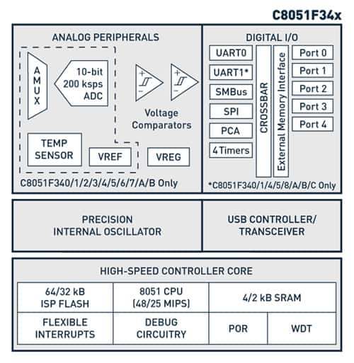
Figure 1: Simple 8-bit MCUs with integrated USB transceivers, such as Silicon Labs’ C8051 series, are a convenient and cost-effective way to implement many embedded designs. (Courtesy of Silicon Labs.)
The choice becomes more nuanced in applications that need to support a specific USB protocol class, such as UART-to-USB or USB-to-SPI. For example, if a project involves updating an existing product with an RS-232 interface to support USB, using a separate USB-UART bridge such as Microchips’ MCP2200 Silicon Labs’ CP2104 or Texas Instruments’ TUSB3410 offers a shorter development cycle and less disruption to the manufacturing supply chain. A stand-alone controller may also be especially helpful if the original design is based on a slower, less-powerful MCU, which may not have the extra processing power (or memory space) to support the added tasks involved with protocol/format conversion.
Application-optimized USB silicon helps fine-tune your design
Once upon a time, designing an embedded system with one or more USB ports was pretty straightforward because most devices (and their respective driver software) were fairly similar, so there was little a designer could do besides follow the reference design. Not anymore. The silicon that sits behind the USB connections found on many modern MCUs has evolved and adapted to meet the demands of the rough-and-tumble embedded systems environment. MCU makers now offer a wide variety of USB-enabled products that feature various levels of hardware acceleration to meet price and performance targets for a wide range of applications.
Perhaps the biggest area of innovation has been in how MCUs perform the requests, acknowledgements, error checking and other functions associated with the USB protocol. In applications where the MCU’s USB interface is used infrequently or for transferring small blocks of data, using software to perform the protocol’s routine signaling and handshaking, packet inspection and error detection tasks is probably fine. However, if your application requires frequent and/or large USB transactions, they may place too heavy a load on the MCU’s limited processing resources.
Until recently, the only solution was to use a standalone USB peripheral controller such as Cypress Semiconductor’s CY7C63801 or Microchip’s USB3300-EZK. Now, several manufacturers offer MCUs with integrated USB controller cores and other features that handle virtually all USB-related tasks.
For example, Atmel’s AVR XMEGA series of 8/16-bit MCUs feature a Full-Speed USB controller core that, in addition to offloading routine protocol functions, uses a Ping-Pong buffer to reduce or eliminate the need to re-send dropped packets (NACKs) for more efficient transfers. This combination allows the interface to run at or close to the maximum 11 Mbps supported by the USB Full-Rate spec (for effective data rates up to 8.72 Mbits/s) while only consuming 7 percent of the CPU’s processing capacity. Many Atmel MCUs also support a proprietary multi-packet transfer mode that uses hardware logic to improve the efficiency of USB block transfers by disassembling the 512-byte data blocks used by most mass storage devices into the 64-byte packets supported by the block transfer protocol. The same mechanism can also reassemble incoming multi-packet transfers into larger data blocks without any CPU intervention.
Further up the silicon food chain, Energy Micro has built several performance enhancements into the USB ports available on many variants of their EFM32 32-bit Cortex-M3-based Gecko MCU families. The activities of most peripheral functions, including serial communications and USB ports, are coordinated by a separate low-power Reflex Bus (Figure 2). In addition to preventing data transfers from consuming any of the main system bus’s bandwidth, events and signals from one peripheral can be used as input signals or triggers by other peripherals and in this way ensure timing-critical operation and reduced software overhead. In addition, a built-in 3.3 V regulator also allows users to run the MCU from the power provided by the USB link.
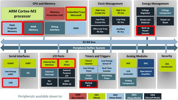
Figure 2: Energy Micro’s EFM32 MCU architecture includes the Peripheral Reflex System, a separate peripheral bus that allows intelligent peripherals (including the USB port) to perform data transfers with virtually no CPU intervention or impact on the main processor bus. (Courtesy of Energy Micro.)
MCU makers are also offering improvements in USB technology that benefit both embedded and more traditional applications. For example, several MCUs now offer on-chip timing circuits that eliminate the cost and PCB real estate associated with the reference crystal (and its associated passive components) traditionally used in the USB interface’ timing clock. Until recently, a crystal-based timing source was necessary to maintain the 0.05 percent accuracy required for the Start-Of-Frame signal exchange that the USB transceiver performs every 1 ms (±0.0005 ms). Silicon Labs introduced the C8051F38x, C8051T62x, and C8051T32x to its C8051 family of 8-bit MCUs that include an on-chip clock-tuning circuit, which recovers its timing information from incoming USB packets. This feature was also introduced on their “Precision 32” SiM3U1xx series in early 2012, an industry-first for a 32-bit processor.
Atmel’s XMEGA series of 8/16-bit MCUs also offers crystal-free operation, and Microchip will be introducing a number of new microcontrollers to its PIC16 family (such as the recently announced “future product” 8-bit PIC16F1459) with either a precision internal oscillator or self-clock-tuning circuit that recovers its timing information from incoming USB packets.
Power matters
In an embedded system, the USB transceiver’s power consumption can represent a significant fraction of the overall power budget, so it is important to understand the factors that govern it. Although the equations in Figure 3 were originally developed for datasheet use for Microchip’s USB PIC microcontrollers, they provide a helpful methodology for calculating the current that is used by an MCU’s embedded USB transceiver. From the relationships of terms PZERO (percent of logic “0s”) and PIN (percent of input traffic) in the overall equation, it quickly becomes apparent that power consumption is application-dependant, since it varies according to the amount and the value of the data transmitted.
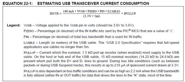
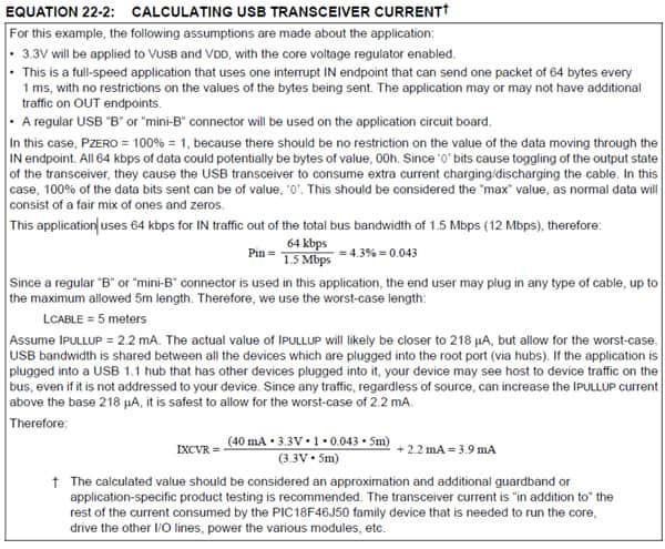
Figure 3: The power consumed by a USB transceiver may be calculated using a relatively simple equation that describes the characteristics of the transceiver, the data it is transmitting and receiving, and the length of the cable to which it is connected. (Courtesy of Microchip Technologies.)
Another interesting thing to note in these examples is that the percentage of IN traffic that is zero has an effect on the amount of current drawn from the bus. Many designers use logical “0s” as their default value for data variables, but it is important to note here that this could actually increase the system current slightly, compared to using “1s”. Also note that this is only a consideration for IN traffic, i.e. traffic that is going from the USB Peripheral to the USB Host.
Many classes of USB peripherals now use USB as the de-facto power source for applications that require 100 mA or less. For applications that require less than 500 mA, the decision becomes a little more difficult because self-powered hubs are less common and many designers still choose to use a separate bus power source.
For applications that require more than 500 mA, the USB specification includes a provision for battery-charging that permits currents of up to 1.5A to be drawn from the system. Unfortunately, since there are relatively few host systems that support the battery-charging specification, peripheral manufacturers are reluctant to produce devices that can take advantage of it. Where you will see this battery-charging specification is in some cell-phone or tablet chargers that are USB based. The battery-charging specification includes an inexpensive (albeit inefficient) way to implement a charger circuit by simply shorting the USB connection’s D+ and D- leads through a resistor (< 200 Ω), a technique you will encounter in most inexpensive USB-based phone/tablet chargers.
To implement the battery-charging specification v1.2 for a Host is rather simple from a signaling standpoint. All that is needed is a voltage source between .5 and .7V that can source 250 µA in that range but will not pull a 1.5k pull-up to 3.0 V below 2.2 V (Figure 4). This voltage source should be attached to D- and enabled when a device is detached, and be disabled when a device attaches. Figure 4 is a simple schematic that will accomplish this with an operational amplifier, a diode, two resistors, and one control line.
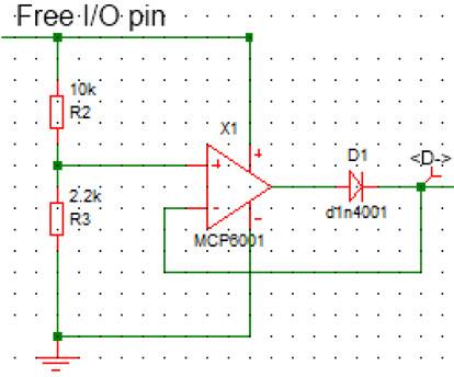
Figure 4: A simple circuit that allows a USB host to engage its optional high-power battery-charging mode. (Courtesy of Microchip Technologies.)
Implementing the BCv1.2 specification on a peripheral is somewhat more complex. It requires two of these voltage-source circuits, two constant-current sinks, and a little more code implementation on the USB peripheral, but it is still well within the grasp of the average embedded designer.
Nevertheless, the reluctance manufacturers to invest in the extra per-unit cost required to support the high-power charging option in their host systems is resulting in a bit of a “chicken-and-egg deadlock” within the industry. With luck, this may change in the next few years if PC makers and other USB-host equipment manufacturers decide to offer desktop-based products that are capable of supporting the higher power requirements of tablets and other mobile peripherals that are closely integrated with the resources of their host system.
USB functionality adds convenience and flexibility to a system by enabling communications with a wide array of USB devices, as well as adding a power option that can provide up to 500 mA in a single cable. As we have noted, USB communications can be designed into embedded systems through the addition of an integrated MCU or a stand-alone USB solution. Among the main considerations with incorporating USB into embedded designs are the size and frequency of USB transactions, the USB transceiver’s power consumption and whether the USB battery-charging specification (v1.2) is involved. We have offered and discussed examples of both integrated USB MCUs and stand-alone controllers. For more information on these parts, use the links provided to access product pages on the DigiKey website.
References and Resources
- The granddaddy of them all, the USB alliance web site: www.usb.org
- If you need a coherent tutorial on the basics of USB, try “USB in a Nutshell” located on Craig Peacock’s www.beyondlogic.org web site.
- MPQ Electronics also publishes an excellent tutorial: “USB Made Simple”, available at http://www.usbmadesimple.co.uk/.
- Jan Axelson, author of "USB Complete" and several other books, has an excellent USB resource web site.
免责声明:各个作者和/或论坛参与者在本网站发表的观点、看法和意见不代表 DigiKey 的观点、看法和意见,也不代表 DigiKey 官方政策。


