The Basics of Pogo Pin Connectors

作者:Jeff Smoot 是 Same Sky 应用工程和运动控制部门副总裁

Pogo pins are compact, spring-loaded connectors widely utilized in electronic systems to ensure reliable electrical connections through their contact points. Structurally, they consist of a cylindrical barrel housing an internal spring, which allows the pin to compress and maintain stable contact pressure. This design gives them a visual resemblance to the classic pogo stick, inspiring the name.

As an interesting note, the original pogo stick toy was developed by Max Pohlig and Ernst Gottschall, combining the first two letters of their surnames to create the product name. Beyond their similar motion and namesake, however, the functional and design relationship between pogo sticks and pogo pins ends there. This article will cover pogo pins in greater detail, including their benefits, common styles, and design considerations.

Pogo pin basics

Pogo pins, first developed at Bell Labs in the early 1970s, were initially designed for semiconductor test equipment due to their suitability for highly precise, miniaturized, and repeatable electrical connections. Their role in the industry has since expanded significantly, with advancements in mechanical stability, current handling, and compact design. These improvements have made pogo pins versatile enough for applications across consumer electronics, industrial systems, and medical devices.

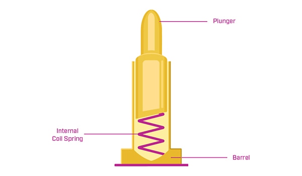
Each pogo pin is composed of three primary parts: a barrel, a plunger, and an internal coil spring. The typical materials are brass or copper alloys, with a nickel coating for durability and corrosion resistance. For applications demanding lower contact resistance, gold and other precious metal plating are often applied. In high-density fixtures, pogo pins are arranged in close proximity to create multiple contact points on a circuit board or within a connector that is frequently mated and unmated. This dense configuration enables efficient, reliable connections that withstand repeated use, critical in many modern electronic applications.

Image of basic components of a typical pogo pinFigure 1: Basic components of a typical pogo pin. (Image source: Same Sky)

Besides cost advantages, pogo pins bring numerous engineering benefits that enhance device performance and longevity:

  • Space and Height Efficiency: Pogo pins conserve valuable board space and reduce assembly height, ideal for compact designs.
  • Durability and Shock Resistance: They are engineered for durability across many mating cycles and are resilient to mechanical shock and vibration.
  • Extended Contact Travel: With high contact travel, pogo pins accommodate thermal expansion and contraction, maintaining stable connections.
  • Precision Assembly: Machine mounting enables precise placement, ensuring consistent and reliable connections.
  • Automatic Alignment: Pogo pins naturally align with mating receptacles, simplifying the assembly process and enhancing reliability.
  • Constant Contact Force: The spring mechanism maintains constant pressure, preventing connection loss under varying conditions.
  • Adaptable Design: Pogo pins are customizable to different board configurations, supporting diverse manufacturing requirements.

Pogo pins are available in a wide range of specifications, including different lengths, diameters, materials, operating forces, current ratings, pad layouts, and plunger styles. This adaptability makes them suitable for a wide array of applications, from challenging industrial environments to everyday consumer electronics.

Pogo pin types and mounting styles

As just mentioned, there are numerous types of pogo pin connection solutions tailored to meet specific application requirements, lifecycle demands, and customization options. Here are some of the more commonly used pogo pin features, which allow engineers to optimize designs based on electrical, mechanical, and environmental needs:

  • High Current: Designed to handle currents typically between 2 and 8 amps, though higher ratings are available for demanding applications
  • High Frequency: Suitable for high-speed applications, capable of supporting data rates up to 10 Gbps
  • Waterproof: Integrated with sealing mechanisms to protect against water and moisture ingress, ideal for outdoor and rugged applications
  • Magnetic: Utilizes magnetic force to establish and maintain a secure, polarized connection
  • Low Spring Force: Designed with reduced spring tension to apply minimal force on contact points, suitable for delicate connections
  • Roller Ball Contact: Features a ball at the contact end to maintain a continuous signal even when there is movement between contacts
  • Thread Screw: Equipped with a threaded design on either the plunger or barrel, enabling a secure fastening to boards or devices
  • Solder Cup: Includes a small solder cup on the back of the pin, allowing for straightforward cable attachment
  • Double-Ended: Contains spring-loaded contacts on both ends, facilitating connections on either side
  • Vertical or Flat-Bottom: Extends vertically from the circuit board, allowing efficient board-to-board connections
  • Right Angle (Horizontal): Configured at a 90° angle to the circuit board, supporting horizontal device mounting
  • Floating: Features a standard spring contact on one end with a curved contact on the other, preventing over-compression while allowing both sides to be used for connections

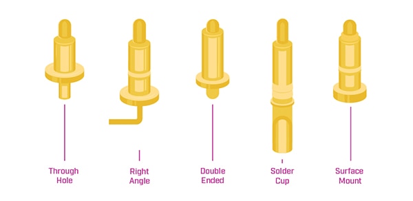
Examples of double-ended and right-angle pogo pinsFigure 2: Examples of double-ended and right-angle pogo pins (Image source: Same Sky)

Pogo pins are generally sourced as individual components, allowing them to be customized for specific board or fixture applications. This flexibility makes them integral to custom interconnect solutions designed to meet precise connection requirements. However, in some cases, off-the-shelf connector arrays containing pogo pins in an insulating housing are available, often complete with mounting hardware, which can streamline the assembly process if they align with design requirements.

For custom board or fixture assemblies, various insertion and mounting options exist to suit different applications:

  • Insertion Types: Pogo pins can be inserted using several methods, including press-fitting, swaging, crimping, soldering, and even solderless options, each offering unique benefits depending on the application’s mechanical and electrical requirements.
  • Mounting Technologies: Mounting configurations include surface mount, through hole, wire mount, and free-hanging styles, providing options for different board designs and interconnect setups.

Image of common pogo pin optionsFigure 3: Common pogo pin options (Image source: Same Sky)

Receptacles or targets

The primary function of an electrical connector is to join or mate two or more components. For traditional connectors, this typically requires a compatible fixture on each end. However, pogo pins offer more versatility, as they can establish connections not only by mating with a receptacle or socket but also by contacting specific target points directly on a circuit board.

These targets may include designated components, plated contact areas on the board, or custom chip receptacles designed specifically for testing integrated circuits. The role of a target is to provide a reliable electrical connection point where pogo pins can make contact and remain stable until the connection is intentionally disengaged.

Final design considerations

To specify the ideal pogo pin, here are some final key considerations to keep in mind:

  • Size and Format: Define the lead size, pin diameter, and format (e.g., round, square, or rectangular) based on spatial constraints and mechanical fit.
  • Contact Material: Choose from materials like brass, copper, nickel, or bronze based on conductivity, durability, and compatibility with other materials in the design.
  • Contact Plating: Select a plating material—such as gold, silver, nickel, palladium, zinc, tin, or lead—based on the desired contact resistance, corrosion resistance, and durability.
  • Electrical Metrics: Evaluate contact resistance and current rating to ensure the pogo pin can handle the required electrical load without excessive loss or heating.
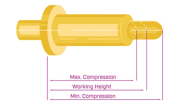
  • Movement: Specify the plunger size, working height (for optimal plunger travel), and dimensional tolerances to ensure reliable contact and compression within the application.
  • Physical Metrics: Consider the initial operating force needed to make contact and the mid-compression force to maintain it, ensuring the pin’s force aligns with the mechanical and durability needs of the design.
  • Environmental Factors: Account for potential exposure to extreme temperatures, shock, vibration, corrosive atmospheres, and moisture. Choosing pogo pins designed for harsh environments will ensure longevity and performance under adverse conditions.

Image of compression as well as recommended working height typically found on a pogo pin schematicFigure 4: Maximum and minimum compression as well as recommended working height typically found on a pogo pin schematic (Image source: Same Sky)

Conclusion

Pogo pins provide a dependable and consistent electrical connection across various devices, thanks to their straightforward yet robust design. This simplicity enables pogo pins to endure thousands of mating and unmating cycles, making them exceptionally durable in high-use applications. Their spring-loaded mechanism also compensates for minor misalignments during connections, ensuring consistent performance even with slight positional offsets. Additionally, pogo pins are both cost-effective and space-efficient, which makes them a preferred connection solution in many modern electronic applications where compactness, reliability, and budget considerations are essential. View Same Sky’s selection of pogo pin connectors available now at DigiKey.

免责声明:各个作者和/或论坛参与者在本网站发表的观点、看法和意见不代表 DigiKey 的观点、看法和意见,也不代表 DigiKey 官方政策。

关于此作者

Jeff Smoot 是 Same Sky 应用工程和运动控制部门副总裁

本文由 Same Sky 的 Jeff Smoot 提供。