Power Over Ethernet Solutions for Smart Building Applications
投稿人:电子产品
2016-05-06
Smart buildings deliver a wealth of benefits to owners and occupants. By using sensors to collect environmental and occupancy data, heating and air conditioning systems can be optimized to keep the occupants comfortable without wasting energy. Lighting systems can respond to occupancy levels and time-of-day conditions to make indoor lighting energy efficient as well. External lighting systems, intelligently controlled, improve safety and security. Smart building emergency systems can identify the fastest and safest paths of egress for occupants or ingress for emergency responders.
If power mains don’t need to be co-located with a smart building’s sensing and control subsystems, deployment flexibility can be significantly enhanced. Using Power over Ethernet (PoE) can increase subsystem deployment options, while retaining a "hardened" communications capability that is more robust, and more secure, than wireless implementations. This article will provide a look at the key elements of a PoE system and will illustrate how they are implemented in an example design.
The Basics
PoE is a power delivery and data communications standard that can provide a convenient source of power to remote sensors, aggregators, wireless gateways, security cameras, and controllers within a smart connected building. Power is delivered safely and can source up to 12.95 W (IEEE 802.3af) and up to 25.5 W for the emerging IEEE 802.3at standard.
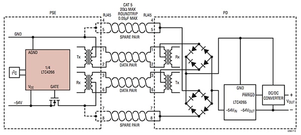
Figure 1 below shows a typical PoE system with the power-sourcing equipment (PSE) on the left and the powered device (PD) on the right. In this example the power source is an Ethernet Switch and the powered device is an office phone. The two devices are connected via the Ethernet twisted-pair cable using two wires for data and the two spare pairs for the delivered 48 V power source. Power is managed by a special PSE controller, on the power sourcing side and a power delivery interface and DC/DC converter on the delivery side.

Figure 1: Power over Ethernet System Architecture (Courtesy of Linear Technology)
One of the main advantages of a PoE system is its convenience for embedded connected devices that require Ethernet connectivity. No additional wires need to be "pulled" to power these systems and the 13 W to 25 W available power is sufficient for most smart building remote devices. A PoE system is also lower cost because no additional wall adapter is required. A side benefit of this approach is that PoE-based devices can be easily powered on or off remotely, which supports smart-power management systems. Note that because the PoE system is separate from the main power system, it can be more easily utilized in power outage situations when a backup power source is provided to power the PoE sections of a smart building. This can be particularly helpful in emergency situations.
PoE applications started with Voice over IP (VoIP) phones and wireless access points but have been steadily growing to include security cameras, RFID readers for secure entry, lighting control, power metering, and environmental sensors and controls. Within smart buildings PoE can be used for aggregation points for multiple wireless devices used for managing room lighting, occupancy detection, heating and ventilation control (HVAC), and the wide range of external environmental sensors used to optimize building management systems. Smart buildings also are using big data to help save energy and improve occupancy safety and comfort.
Implementing PoE systems
As seen in Figure 2 the Linear Technology LTC4266 can implement the PSE portion of the POE system. In fact, the LTC4266 is a quad device that can source power to up to four separate PD subsystems. This makes the LTC4266 ideal for Ethernet hubs and concentrators where multiple Ethernet connections are sourced. An important feature of PSE devices is the ability to differentiate between legacy Ethernet systems that don’t support POE and those that do. A device that doesn’t support PoE could be damaged if PoE voltages are supplied, so a simple detection scheme is used that identifies a PoE-supported device. A valid PD presents a 25 kΩ common-mode resistance at their inputs, so it is easy to determine if power can be safely supplied.

Figure 2: POE System with a Linear Technology LTC4266 as the PSE. (Courtesy of Linear Technology)
The LTC4266 is configured and controlled via a SMBus/I²C 2-wire interface. This interface can be used to configure many of the features of the LTC4266 as needed by the target application. Settings for current limits, overload limits, current/voltage monitoring, and interrupt signal selection are all programmable via the serial interface. Commonly, a power-management MCU is used in conjunction with the LTC4266 to create an intelligent power management system that monitors and controls local power delivery and informs higher level system elements of a power event.
Implementing the PD Interface
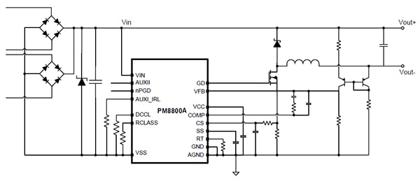
Another key element of the system is the PD interface. This portion of the PoE system manages the power provided by the PSE source over the Ethernet cable. An example device that provides this important function is the STMicroelectronics PM8800A PoE-PD interface. This device integrates several PoE-related functions to simplify the design of the PD subsystem. Figure 3 shows a typical PD implementation using the PM8800A and the external components needed to complete the design.

Figure 3: PD Subsystem Using the ST PM8800A (Courtesy of STMicroelectronics)
The PM8800A is a monolithic device embedding an IEEE 802.3af compliant PD interface together with a current mode pulse width modulator to be used in all PoE-powered devices. In addition to the standard IEEE 802.3af features, the PM8800A provides features for the emerging IEEE 802.3at standard, specifically targeting appliances or systems requiring higher power with respect to the 12.95 W allowed by standard PSE devices. The addition of under-voltage lock-out, in-rush and continuous current limits, and high-voltage regulation during startup and a power-good indication makes for a very robust design.
Another example of a full-featured PoE PD interface device is the Texas Instruments TPS23752PWP Power over Ethernet Controller. It implements the industry standard functions, but also includes a special Sleep Mode capability. The Sleep Mode permits power savings at night (or some other system-driven criteria) by turning the active load circuits off while maintaining enough functionality for the PD to respond to a local power-up request. The Sleep Mode is initiated when the sleep input is driven low. The Sleep Mode is latched by this event and the converter is disabled. The TPS23752 signals the PSE that it wants to remain powered during sleep by drawing enough current to satisfy the IEEE 802.3at MPS requirements.
A complete PoE System for a smart building environmental monitor
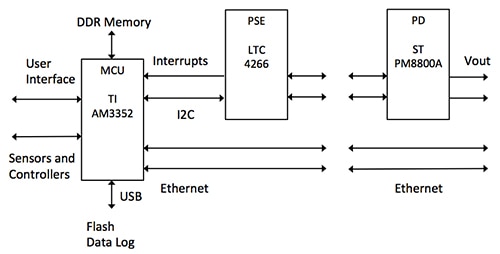
A complete PoE system appropriate for a smart-building monitoring subsystem requires a significant amount of management and control so often an MCU is used to assist in the management of PoE delivery. Some buildings, manufacturing-oriented buildings in particular, may also want to use Industrial Ethernet as part of the communications system when high reliability and predictable network traffic are required. An MCU that supports industrial Ethernet, such as the Texas Instruments AM3352 can often fill this important role. The block diagram for a smart building using intelligent monitoring and PoE in an industrial setting is shown in Figure 4.

Figure 4: Block Diagram of Smart Building Monitor Subsystem
The AM3352 MCU is powerful enough to implement a wide range of intelligent algorithms for sensing and controlling energy use for lighting, HVAC, signage, occupancy, material transport, and process control. A graphical user interface makes it easy for a local systems manager to view operations and the industrial Ethernet ports provide fast data movement as well as a remote management port to monitor subsystem activity. A local data logger can record critical events for further analysis. The LTC4266 PSE device delivers power, under control of the MCU to selected PD destinations. An ST PM8800A provides the PD function at all remote sensor and monitor subsystems. These subsystems are distributed throughout the building and the materials processing system and can be powered independently from the main power system creating a much more robust and fault-tolerant implementation.
In conclusion, PoE provides smart buildings an efficient method for extending the reach of sensors, cameras, and emergency systems without the need for a traditional power source. When combined with a powerful MCU and Industrial Ethernet, PoE delivery systems become an integrated part of a complete energy-management system that makes smart buildings even smarter.
For more information about the parts discussed in this article, use the links provided to access product pages on the DigiKey website.
免责声明:各个作者和/或论坛参与者在本网站发表的观点、看法和意见不代表 DigiKey 的观点、看法和意见,也不代表 DigiKey 官方政策。


