Power Management is Key to Connectivity
投稿人:Convergence Promotions LLC
2012-03-20
As network connectivity spreads to more and more devices, the ability to get high-speed data and power for these high-speed modes is critical. The control of dynamic power, especially with new low voltage operating modes, requires that devices have interactive control of their total power supply. This includes multiple power levels on chargers and DC-DC converters for times when networking interfaces are either being used or sitting idle.
The incorporation of IEEE 802.3 criteria into designs has had an impact, not only on the data head end but all through the design in order to handle peak power management. This article will examine the controller ICs and peripherals available for retrofitting existing designs to these new standards. These power solutions exist at both the embedded design and the system levels.
Need for power management
Networking products, unlike most computing equipment, fall into the infrastructure category. This means that the products and capabilities need to be accessible not only on a 24/7 basis but also in all locations. This need for 24/7 availability started when the utilization of the resources was also on a 24/7 basis. As computing has increased in speed and data rates have similarly risen, the networking devices no longer see a continuous flow of traffic. This packet-traffic-based flow impacts both the peak power utilization of the PHY for the network connections, as well as the baseline power response of the systems.
These issues are being addressed with revised specifications such as IEEE 802.3az (also known as Energy Efficient Ethernet or EEE) which specify power-down modes as well as hot swappable and redundant power supplies, all of which help enable continuous operation and on-board power management for handling the multiple voltages that are now part of the network interfaces.
A global perspective on power
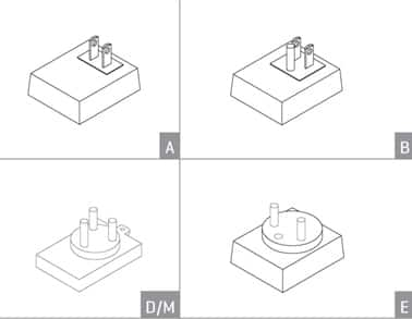
As the networking world migrated from captive corporate computing to distributed, cloud-based computing, the equipment has also had to adapt. Regional models of equipment have given way to design with a single SKU for multiple locations. This presents a challenge in that voltage standards vary between nations. Not only does the voltage range from 110 to 240 volts at 50 Hz to 60 Hz, but the physical interconnect format (wall plug) varies. Figure 1 shows some of the international power plugs that are now required to support most infrastructure type equipment. Further details on power by country can be found in the CUI World Plug and Voltage Application Guide.

Figure 1: CUI World Plug connectors (Courtesy CUI Inc.).
System power
One solution for addressing growing diversity is to use a custom power supply. While these have been available in multiple form factors and with multiple efficiencies, they have design and qualification issues that inhibit use in a variety of products. The alternative is to use a standard power supply in all products. However, this may result in a restriction on the voltages and currents available for a system design as features are added to a system.
A new alternative is available: a custom supply that uses modular components in a standard enclosure. Excelsys Technologies, Ltd. has a 1U enclosure power supply chassis that supports high efficiency (up to 90 percent) Xgen Series configurable power supplies using power modules with regulated outputs from 1.5 to 28 volts and output currents from 3 to 50 amperes. This flexibility not only allows for the creation of redundant power control for a design through the use of multiple modules, but also provides for power optimization of the computing and network interface cores, I/Os, and memory functions. Figure 2 shows the Excelsys Xlite power supply in a slimline configuration with multiple plug-ins. The use of standard modules allows for the creation of a custom solution with all of the certifications for use in place.

Figure 2: Excelsys’ Xlite configurable power supply (Courtesy Excelsys).
On-Board power
One of the key aspects of the EEE specification is the ability for the network PHY to power-down and restart based on the network traffic and handshake with the other end of the line. The technology to do this is found in semiconductor processes below the 90 nm node. In these technologies, the standard operating power supply level is not just a single five volts; these systems have a mixed voltage control ranging from 1.3 volts up to five volts, with primary stops at 1.5 volts, 1.8 volts, 2.7 volts, and 3.3 volts.
The main connection point for the network is the PHY or physical layer block. This drives either the antenna system for wireless applications or the wire and optical connectors for standard Ethernet applications. These PHY blocks are available in multiple forms: integrated into the networking controllers; standalone as a single port transceiver; and as multi-port transceivers. These parts address multiple connection protocols, typically a dual 10/100BT PHY or a triple 10/100/1000BT PHY as found in numerous network PHY transceivers.
10/100BT PHYs, such as Texas Instruments’ TLK110, have a simple interface to the Ethernet MAC block and the external connector/transformers/magnetics, as shown in Figure 3. These units support the new 3.3 volt interface, and operate best when connected to fixed voltage analog and digital supply regulators. The part features an internal 1.5 volt power regulator. This internal regulator supports the low-power mode and high-speed logic for the chip. The I/Os have both a system 3.3 volt and an analog 3.3 volt supply, along with ground pairs. This allows for not only isolation of the noise from the two different paths, but also minimized loading on the power regulators for those paths.

Figure 3: Texas Instruments’ TLK110 Ethernet PHY (Courtesy Texas Instruments).
When the design uses a single transceiver, power management is pretty straightforward. With multiple connections (4, 8, or up to 48 per block), the issues of peak power management and power-down cycling are more complicated. These systems require the use of internal regulators to help support the external power management for the rows of connected devices while the logic stays internally managed.
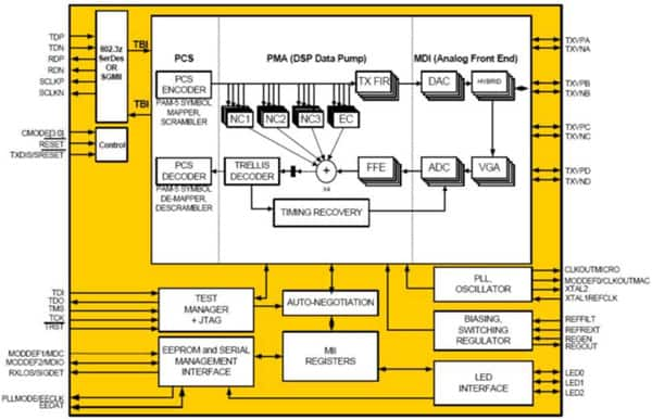
High-speed, single ported PHY transceivers such as Vitesse Semiconductor Corporation’s VSC8221 10/100/1000BT PHY (see Figure 4) also incorporate line interfaces and SerDes into the part. This is supported by an integrated 1.2 GB SERDES and a 150 M twisted pair interface for CAT5 cable. These blocks both have dynamic power control and can be stacked in dense form, as their power allocation is under one watt per chip (700 mW). As an advantage to board design and application, the part does not require either transformers for the CAT5 connection (which can be done with capacitors) nor for power regulation through a transformer. Both fixed and adjustable power regulators (not PWM, but DC) can be used with the device with minimal heat sinks.

Figure 4: Vitesse Semiconductor’s 10/100/1000 PHY block diagram (Courtesy Vitesse Semiconductor Corporation).
Power regulators
As there are supply compatibility issues with legacy designs, in most cases you cannot use a new master power supply that has the lower voltages output. In these cases, you have access to five and twelve volt power. To support the new designs, there are two types of regulator options: fixed and adjustable. A full listing of the variety of regulators available can be found on DigiKey’s website.
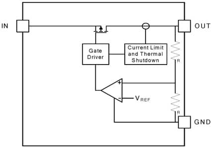
Products like Diodes Incorporated’s AP7333, 300 mA output low dropout linear regulator, are simple three-pin devices that have a fixed output voltage of 3.3 volts, thermal shutdown control, short circuit protection, and fast transient response to changes in the device load. These loads include startup and wakeup circuits for the EEE PHY and MAC pairs. The device has a single ground point, an input supply pin – in this case, two to six volts – and the output voltage. A schematic of the internal block diagram of a typical fixed voltage regulator (Diodes’ AP7333) is shown in Figure 5.

Figure 5: Diodes’ AP7333 fixed voltage regulator (Courtesy Diodes Incorporated).
These regulators, with fixed output voltages, are being used for new designs that have optimized components and need to interface to the five volt supplies. The new interface voltages are 3.3 volts for the PHY and a mix of 1.8 volts or 1.5 volts and 3.3 volts for the MAC of the network block. The key parameters for the selection of the regulators are the amount of drop-out voltage that is allowed and how much current can be provided.
These fixed regulators, like the adjustable type, come in a variety of packages that are based on the total power that can be handled by the device. They range from small surface-mount devices through larger through-hole devices that have mounting points for heat sinks directly on the device.
Adjustable voltage regulators allow the board and system design to set the output level and the corresponding output current. These devices are useful if designs will utilize a variety of parts for a similar function. For example, if you are building a system with a 10/100BT PHY based on a particular technology and supplier, you may need 3.0 volts, 3.3 volts, 2.5 volts or a combination of those voltages to run the part. Using an adjustable regulator, you can simply change the resistor values for the set point and have the output at a new level.
This feature can be especially important in certain applications. Backplane and ATCA, CAT5/CAT6, and optical drivers all need different voltages and currents for the I/O interface. The PHYs generally support all three of these output varieties.
Another place where adjustable regulators are useful is on the higher-voltage supply rails. Supplies of 18 to 24 volts are either regulated down to 12 volts or 7.5 volts depending on the type of system used. The higher voltage regulation applications have typically higher current requirements than the lower voltage level regulators. As a result, providing the intermediate regulation to supply the load for the sub-five volt regulators is done with application-specific tailoring of the voltage and current levels of the transceiver configuration.
Retrofitting designs
For designs that are being retrofitted as existing networking platforms, adjustable regulators are useful. The typical retrofit for a design involves taking an existing 10/100BT network controller and updating it to 10/100/1000BT Ethernet. For designs that are already 10/100/1000BT Ethernet applications, the boards are modified to use EEE PHY blocks in order to take advantage of the lower-energy platform.
Based on the function of the PHY block, devices such as the Vitesse VSC8601 may supply multiple voltages for the system. The PHY itself uses a single 3.3 volt supply. However, the MAC and signal connections need 5 volts, 2.5 volts, and 1.8 volts depending on the type of system. These applications for retrofit include not only cable connections (CAT5 or CAT6) but also backplane and ATCA functions.
These functions require that the networking components automatically detect and support inline-powered devices in the network. The inline power detection capability allows a system function such as an IP phone, wireless access point, or other device to receive power directly from the Ethernet cable. This capability is similar to standard office digital phones that receive their power from a PBX office switch via telephone cabling. It allows the end device to eliminate the need for an external power supply, but it does put the current load burden on the PHY. For long lines (near the 150 meter limit) this can be a strain on the power management for the PHY itself.
Inline-powered devices can remain active during a power outage, since the networking components are usually connected to an uninterruptible power supply (UPS), battery, backup power system, or generator so that they can stay active in the event of an outage. The peak power of the cable load and the inline-powered devices must be equal to or less than the power factor delivered by the voltage regulators.
Summary
Network connectivity is facing the same low-power constraints as computers and portable devices. This constraint results in the need for active power management of different modes of operation, and more importantly when and how data is being transferred. Compliance with new energy efficiency standards coupled with lower power peripherals will help bring the overall cost of connectivity to a more manageable level.

免责声明:各个作者和/或论坛参与者在本网站发表的观点、看法和意见不代表 DigiKey 的观点、看法和意见,也不代表 DigiKey 官方政策。


