Power Line Communications: A Viable Consumer Link
投稿人:Convergence Promotions LLC
2013-05-29
Power line communications has been around for a long time and most of us were first exposed to this technology, with its early use for home automation and remote control of appliances. It uses the AC power lines as both a source of power and as a communications medium.
Initially introduced to the public as what is now called the X10 protocol, the benefits of using the same wires power wires for communications have become well understood and extensions of this technology are used by power utilities, as well as for computer networking and distributed audio streaming within a building.
This article looks at power line communications technologies and the devices engineers can use to implement it. It examines some of the history and popular protocols with their benefits and limitations, and discusses issues to be aware of when deciding if power line communications is a good fit for your applications.
All parts, datasheets, tutorials, and development kits referenced in this article can be found online at DigiKey’s website.
From whence it came
The power utilities discovered early on that in addition to delivering raw high-voltage AC power through an extensive network of cables, switches, transformers, and circuit breakers, they also needed a way of communicating. In the 1920s and 1930s, people were not as dependent on electricity as they are today, so when power went out it could routinely take days or even weeks to send crews to find and fix power faults, especially in remote areas.
The most basic need for remote data gathering drove the early systems. The simplest implementations use narrow band 15 to 500 KHz carrier waves for rudimentary on/off keying for long haul remote data measurements over high tension power lines. These low-frequency RF signals are capacitively coupled at relatively low amplitudes (compared to the kilovolt levels of the AC power), and do not interfere with the 60 Hz power and timing signals used in early electric appliances. (For example, before crystals, early clocks would get their time reference from the 60 Hz power line and high frequencies did not get through the transformers that converted the high-tension voltage to standard 120 volts used today).
Modern power generating stations, sub-stations, remote switches, transformers, and even circuit breakers have communications built-in so that dynamic switching, reconfiguring, fault detection, and mediation can take place. A circuit breaker can automatically retry a few times before signaling a fault to the main monitoring station. If a temporary short or surge was the cause, power is restored without any intervention or service calls from humans.
Higher bandwidths using modern telephony, microwave, fiber optics, cellular and internet-based telemetry and control are supplanting the older power line modulators for links between generators and switching stations. However, interest is growing and standards are developing for the utilities to use power line communications as a way of reading the newest generations of power meters. In addition, this technology is still alive and ripe for deployment for homes and buildings featuring automation and energy management.
Simple to implement
The original X10 protocol is still very usable and ready for new designs. It has become an international and open industry standard for home automation. Based on multiply redundant, slow bandwidth, true-compliment signaling, a large base of X10 modules and controllers has been and is still available today for use in homes, apartments, and commercial buildings.
This large installed base is beneficial in two ways. If you design a transmitting controller, you can interoperate with many different end devices. In addition, the end devices are already certified and have agency approvals. This can save time, cost, and avoid making you reinvent the wheel.
Note that X10 is useful for control-intensive rather than data-intensive applications. Since data rates are slow (less than 30 baud), this is not a usable standard for data files, audio, video, or Internet.
However, X10 is very useful for switching power on and off for lights and appliances, as well as for incandescent light dimming. With the continued emphasis on lower energy usage and energy management, the additions to the international standard that support bi-directional communications and multiple transmitter systems open the door for modern applications such as alarms, thermostats, security camera platform controllers, motorized window louvers, and solenoid controlled heater/cooler venting.
Virtually any low-cost microcontroller without high-end DSP functionality can drive the X10 protocol. It uses a relatively slow carrier frequency of 120 kHz that can easily be synthesized by a counter/timer or PWM on a low-cost MCU.
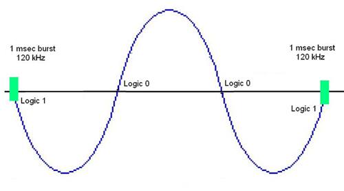
A logic 1 is represented by a single millisecond burst of the 120 kHz carrier at the zero crossing point. A logic 0 is the absence of the carrier at the zero point (see Figure 1). The carrier should be active within 200 μsec of the AC zero crossing point, which is chosen because it is the ‘quietest’ point from a signal-to-noise ratio point of view.
A necessary function for any control/status network is addressability, and up to 256 devices can be connected on a single, two-phase, or three-phase power line. This is broken down as a ‘House Code’ (A-P) and a ‘Unit Code’ (1-16) to make it simple for a typical homeowner to understand and assign addresses.
House codes use a 4-bit binary value (see Table 1), while unit codes share a 5-bit address space with the commands (see Table 2). The 11 bits in a data block consists of a 2-bit start code, a 4-bit House code and a 5-bit Unit code (or Command code).


Table 2: Unit codes and commands share a 5-bit binary code (Courtesy of X10).
Each bit is followed by its compliment bit (see Figure 2), so every bit is transmitted twice. Each Block is also transmitted twice with three power line cycles separating the transmissions (except for BRIGHT and DIM commands).
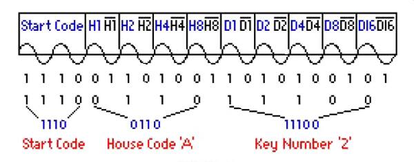
Figure 2: Every bit of the House code and Unit code is followed by a true compliment representation at the following zero cross. This redundancy helps protect from noise-based false triggers and codes (Courtesy of x10).
As a communications protocol, this is very simple and can easily be coded into even small 8-bit microcontrollers to allow low-cost plug-and-play compatibility with a widely deployed standard. External circuitry is minimal as well. All that is needed is a zero cross detector (transistor) and a high-voltage coupling stage (typically a polystyrene capacitor) and you are on the network.
Roll your own non-standards
Several ICs exist that allow generic access to the power lines as a communications medium. These peripheral-style modulator/demodulator chips not only allow you to implement standard protocols but also to design your own proprietary ones.
Take for example NXP Semiconductors’ TDA5051AT/C1 power line modem IC. It is a modem peripheral chip that uses amplitude-shift keying to achieve 600- or 1200-baud data rates over household 120 or 240 VAC household wiring.
The small 16-pin SOIC can easily be buried into small outlet-sized designs and the five volt operation keeps it compatible with many low-cost legacy processors. Either a host microcontroller’s master clock or external crystal can be used to generate an accurate time base that uses a shaped signal spectrum centered around 132.5 kHz with a 20 dB variation at 1500 Hz separation (see Figure 3).
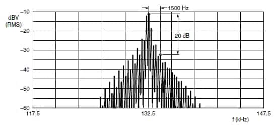
Figure 3: The NXP Semiconductors part uses a shaped spectral pattern to modulate data centered around 132.5 kHz (Courtesy of NXP Semiconductors).
The chip couples to a power line network using an LC network for either isolated or non-isolated applications; it contains internal drivers that can push out 120 dBμV RMS into a 30 ohm load. It functions as a state machine with internal AGC feeding an A/D for reception and decoding and a D/A converter for transmission levels. It is driven by internal control logic (see Figure 4). Power-down pins allow sleep modes for power savings. A training module from NXP Semiconductors is available on DigiKey’s website and provides a good overview of the TDA5051.
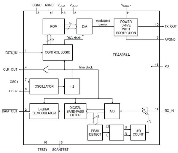
Figure 4: As a state machine driven peripheral, the TDA5051 can be bolted on to virtually any microcontroller’s serial transmit and receive bit streams (Courtesy of NXP Semiconductors).
Cypress Semiconductor also offers an interesting single-chip, five-volt power line communications transceiver peripheral chip. The CY8CPLC10-28PVXI achieves a reliable 2400 bps transfer rate according to Cypress. The included PHY and protocol stack are on-chip; as a peripheral device, it communicates with a host processor through an I²C bus. It uses FSK as a modulations scheme, and there are reference designs that enable this part to transmit data over 120, 240, 12, and 24 VAC power lines. It can also transmit signals riding over a DC level (see Figure 5).
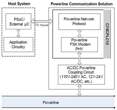
Figure 5: As an independent peripheral Cypress Semiconductor’s CY8CPLC10 communicates with a local microcontroller via I²C, completely unburdening the host from any power line protocol responsibilities (Courtesy of Cypress Semiconductor).
Another power line modem comes from Maxim with its single-chip MAX2990ECB+. This part is a bit more complex and is based on an Orthogonal Frequency Division Multiplexed (OFDM) type of modulation and demodulation scheme. Like the NXP part, it communicates in half duplex, but unlike the other part’s 600- and 1200-baud data rates, this part achieves up to 100 kbits per second. Touted as a SoC with an integrated physical and media access control layers (MAC and PHY), the chip also includes an internal 16-bit RISC microcontroller with 32K of flash and 8K of RAM utilizing a 4K dual-port RAM block shared by the internal MCU and the PHY (see Figure 6).
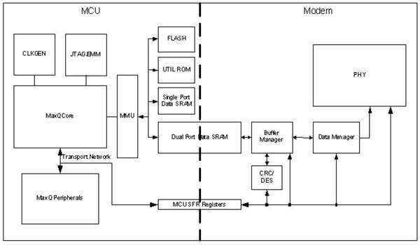
Figure 6: The Maxim MAX2990 uses a dual -port memory architecture along with an embedded microcontroller core to share buffer memory with the buffer managed modem. CRC error detection and encryption are handled by the modem (Courtesy of Maxim).
Included inside the MAX2990 are a forward error correction unit and a fast hardware-based encryption and decryption unit to aid in data recovery under changing conditions and security respectively. A Carrier Sense Multiple Access/Collision Avoidance scheme is used to arbitrate channel access, and SPI, UART, and I²C ports are available, as well as general purpose I/O.
At the core
An advantage to using a standardized microcontroller core is a community of experienced designers, coders, and tools; an Atmel SoC based on the 8051 core is a prime example. The ATPL210A-A1U-Y includes and enhanced 8051 core with up to five times the speed performance of the legacy twelve clocks-per-cycle part. It also includes a power line carrier modem for 50 and 60 Hz mains with impressive data rates up to 128,600 bits per second, based on differential BPSK, QPSK, and 8-PSK types of modulation.
This is not your dad’s 8051. This 120-pin SoC includes a MAC coprocessor to offload the main CPU and 32Kx8 of on-chip SRAM that maps as code and I/O space (see Figure 7).
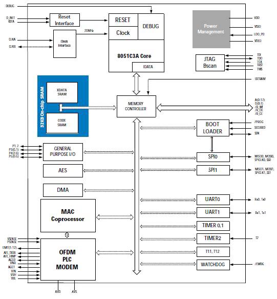
Figure 7: The embedded 8051 enhanced core is combined with on chip memory and advanced peripherals to create a SoC that caches program memory automatically from serial Flash or EEPROM into its dual function (code space and data space) memory. A high performance OFDM power line modem is also in there (Courtesy of Atmel).
Entry for debugging is provided through JTAG, and the part can auto bootload from serial flash into SRAM. Embedded DMA, 128-bit AES, UARTs, SPI, I²C, programmable watchdog, and general purpose I/O are all available for the non-power line based communications processes. This part can function as a standalone power line transceiver.
Power to develop
In addition to making dedicated power line modulating peripherals and SoCs, several IC makers support power line modulated data transmission within their development environments. The CY3273 development kit for Cypress Semiconductor’s CY8CPLC10-28PVXI (discussed earlier) demonstrates power line communications using lower voltage (12 V/24 V) AC and DC power lines. You can use these parts for 120 and 240 VAC designs as well.
NXP Semiconductors also supports its TDA5051AT/C1 with the OM13313,598 power line modem demo board. An application note and reference design is also available from NXP.
Another example comes from STMicroelectronics is the EVALST7590-2 evaluation kit to support its ST7590T STarGRID™ power line modem technology based on narrow-band OFDM modulation. Featuring 96 subcarriers for BDPSK, QDPSK, and 8-DPSK submodulation, the PRIME-compliant PHY can operate in the 72 kHz carrier-based CENELEC A Band with bit rates up to 128 kbits per second.
As a precaution, the power line interface electronics are shrouded in an insulating Plexiglas enclosure and a ribbon connection scheme is used to drive and control the modulators safely (see Figure 8).
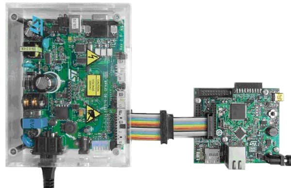
Figure 8: With high voltage power lines as the communications medium, the STMicroelectronics EVALST7590 development board uses a protective Plexiglas covering (Courtesy of STMicroelectronics).
Microchip’s development environment supports power line modulated communications with its AC164145 and AC164142 daughter boards for the Microchip Explorer 16 development boards. These plug-in boards provide a 7.2 kbits per second data link using an analog front-end driven by their dsPICTM33F digital signal controllers which act as a software-defined modem.
This application targets the BPSK utility band running at 6 kbits per second for automated meter reading (AMR) applications, energy consumption monitoring, and individual appliance access and control. As a precaution, a well-insulated high-voltage adapter cable couples it to the power line.
DSP at the heart
High-end networking, audio streaming, and video over power line applications are much tougher to design. In these cases, DSP processing and algorithms do the data recovery and even error correction with high-speed data streams. One company well entrenched with DSP is Texas Instruments. They offer chips and development kits with support for power line communications.
Texas Instruments’ TMDSPLCMODA-P3X is actually a kit add-on supporting their Piccolo™ series 32-bit DSP processors. It uses a USB or serial port to communicate with lighting control power supplies designed for advanced LED lighting.
Texas Instruments also has the TMDSSOLARPEXPKIT Solar Energy Explorer kit for the Piccolo series, which takes aim at solar panel and grid-tied microinverter designs. Modern solar panels can communicate over power lines to read energy per cell and to verify operations from a remote location. The TMS320F28035 processors are used in both of the TI development kits mentioned.
Concerns and issues
One issue to be aware of when planning for a power line based communications scheme is handling multiple phases. Most residences have 120/240 VAC service which uses two 120 VAC lines 180 degrees out-of-phase with each other. Three-phase systems are also quite common, separating 120 VAC phases by 120 degrees. In all cases, the issue arises when a transmitter is on one phase and the device receiving the data is on another phase – the signal may not get through. While capacitive coupling between phases can pass modulated signals, it is not reliable. The only reliable way is to have phase repeaters or to have a transmitter for each phase.
Another issue and concern is that in order to be useful and reliable, bi-directional communications are needed. In an energy management system that requires adhering to a peak demand load requirement, if you send a command to turn something off, you had better have an acknowledgement in return. Collision detection and avoidance schemes play into this to maintain reliable communications.
One other possible concern is that very noisy appliances like old blenders and brush-based motors can put out so much noise on the AC lines that a signal is hard to recover. Good filtering can help as can multiple carrier frequencies, but this is a concern.
From a design point of view, the changing impedance of the power line can wreak havoc with delivering transmit power to the lines. Every time something turns on or off or changes its mode of operation, the power line characteristics can change. Even a neighbor’s appliance can interfere.
Conclusion
Power lines are readily available in older structures and will most likely be present in new structures as well (unless we, as a society have a “come to Tesla” moment). As a result, devices that draw power can also communicate wirelessly since no new wires are needed.
Power line communications has its concerns and drawbacks, but it has proven to be a relatively reliable and effective way of communicating. It is well positioned to be used in the next generation of appliances and devices that will need to be more energy efficient.

免责声明:各个作者和/或论坛参与者在本网站发表的观点、看法和意见不代表 DigiKey 的观点、看法和意见,也不代表 DigiKey 官方政策。


