MCU Vendors Gear Up Protection for Mission-Critical IP
投稿人:电子产品
2015-06-17
Many designers still believe that that they can enable “pretty good” IP security by prohibiting debug access to the MCU. After the development cycle, the debug path (JTAG or SWD) is blocked by using a user-configurable setting. This approach, however, is really not much of a deterrent to even moderately skilled IP pirates who want to reverse engineer the product.
Simply blocking debug access does not prevent reading device memory out of the locations that contain critical software IP. Although there are several approaches to solving this problem, one of the most effective is to isolate critical IP in by creating internal hardware and software barriers to entry.
Before describing two solutions, however, it is worth enumerating the developments that are making the embedded space increasingly dangerous.
Appliances such as dishwashers, refrigerators, and home-automation systems are using more and more powerful MCUs to implement advanced diagnostic and convenience features. The software IP that implements these features costs time and money to develop, which means that effective steps are needed to prevent theft by competitors.
Protecting product IP is much easier when the appliance or device operates more or less autonomously. The “big data” trend – collecting terabytes of information that can be mined for marketing purposes – has given embedded systems the critical task of originating that data and transporting it over Internet of Things (IoT) connections. This major shift in interconnectedness adds to the imperative for protection.
A third trend – one not often mentioned – is the widespread adoption of open-source software. Engineers like open source because it is typically less expensive to acquire, easy to use, and shortens the design cycle. Linux is becoming widely used in many industry segments, for example, but open-source software also includes code such as communication stacks. Despite its advantages, open-source software is more vulnerable than proprietary systems because anyone – including IP pirates – can acquire the source code, analyze it, and modify it.
Hardware security
A time-tested approach to implementing security is to include a separate security processor – often an MCU – with its own carefully controlled access and execution environment. The security subsystem may, for example, be an encryption engine. In addition to adding security, the engine offloads the main MCU from the task of executing encryption algorithms in software. In this approach, an internal descriptor-based DMA is typically employed for efficient programming of the security association data and packet pointers. An intelligent state machine schedules the crypto engines based on the protocol selection and packet boundaries.
Although highly secure, using an additional processor has disadvantages. The three most prominent are: 1) the additional bill of materials (BOM) cost; 2) reduced performance of the overall system; and 3) lack of programmability. Other options are available that are conceptually similar to this approach.
ARM TrustZone
For 32-bit designs, ARM Holdings Ltd. has developed a technology called TrustZone that goes a long way toward alleviating these disadvantages. TrustZone refers to security extensions that can be implemented in a number of ARM cores – and is tightly integrated into its Cortex-A processors.
ARM’s system-wide approach to security begins in the execution environment and is extended with specific TrustZone IP blocks specific to the company’s AMBA bus and the AXI bus. The system approach makes it possible to secure peripherals such as memory and crypto blocks.
The TrustZone architecture essentially segregates a hardware subset of the ARM-core-based MCU by defining processors, peripherals, memory addresses, and even areas of cache to run as “secure” or “non-secure” hardware. TrustZone technology can dynamically expose the full MCU to secure software, or to a subset of that MCU to normal software.
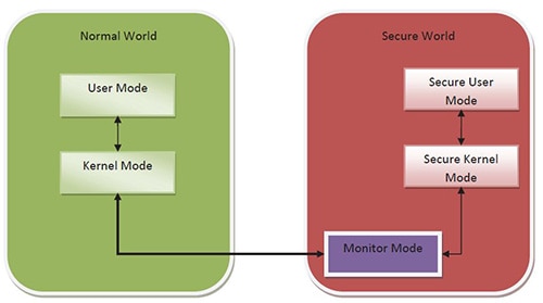
TrustZone accomplishes this by splitting processor cores into two virtual cores, one operating in a normal world and the other working in a secure world (Figure 1). This mechanism essentially creates a new level of execution privilege in addition to the traditional demarcation of user and kernel modes. Transitions between the two worlds are carefully controlled by monitor mode software.

Figure 1: ARM’s TrustZone architecture is conceptually based on creating virtual cores. (Courtesy of Texas Instruments)
Any MCU vendor with ARM-based products has the option to implement TrustZone. Texas Instruments provides support for TrustZone-enabled applications with its KeyStone II System-on-Chip (SoC) architecture, which features an integrated ARM Cortex-A15 cluster. Since TrustZone is integrated into ARM’s Cortex-A processors, members of TI’s more economical Sitara family, which is based on the A8 core, all support TrustZone, including the AM3352ZCE27.
Among the other TrustZone-enabled products are Atmel’s SAMA5D4 Series of 32-bit MCUs, including the ATSAMA5D41A-CU and Freescale Semiconductor’s i.MX6 Series, including the MCIMX6X1CVK08AB.
Because it is hardware based, TrustZone provides a robust foundation upon which the upper layers of secure software can be built. There are three foundation elements involved in creating a TrustZone-protected application.
- Trusted Execution Environment (TEE) – A software stack running within the secure world, plus the communications functionality needed to enable secure-world software to interact with normal-world software. TEE software typically consists of a small microkernel and APIs that allow secure software to communicate with the larger, user-centric software.
- Security-aware applications and secure services, or Trusted Applications (TA)
- The Secure Monitor that acts as a virtual gatekeeper controlling migration between the domains.
The physical core switches between the two virtual cores by invoking a new processor mode called monitor mode. Monitor mode can be entered from normal-world mode either by activating ARM’s Secure Monitor Call (SMC) instruction or from a subset of hardware exception mechanisms. Configuration of the IRQ, FIQ, external Data Abort, and external Prefetch Abort exceptions can all cause the processor to switch into monitor mode. These interrupts can also be assigned higher priorities to guard secure-world software against denial-of-service attacks.
TrustZone software
TrustZone hardware is complemented by a software architecture that implements similar partitioning. In this architecture, all security-related functions, including interfacing with secure peripherals are the province of the secure world and the normal world handles other tasks.
The software that executes within monitor mode typically saves the software image of the current world and restores that state at the location to which it switches. It then performs a return-from-exception command to restart processing in the restored world.
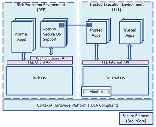
The secure world hosts all secure applications and provides services that are carefully brokered through monitor code to clients in the normal world. The secure world only can only run code that has gone through extensive vetting. Figure 2 shows TrustZone’s software architecture.

Figure 2: TrustZone software architecture. (Courtesy of ARM Ltd.)
It is not necessary to develop complex software to provide meaningful security with TrustZone. In fact, sometimes writing complex software can undermine security goals by introducing and hiding additional vulnerabilities. The choice of implementations depends on use scenarios and can range from a sophisticated fully pre-emptible OS to a set of passive libraries that provide on-demand services to the normal world. The TrustZone architecture provides a secure timer and security-aware interrupt controller for building a pre-emptible secure OS.
A secure boot is essential to protecting IP because the MCU is in a relatively compromised environment when all components are loading. On-chip ROM code plays a key role in the TrustZone boot process. Its role is to store a trusted software image that is signed with the OEM’s private key. The public counterpart of the OEM’s private key is programmed into the MCU only once during manufacturing.
The trusted OEM software image boots the secondary boot loader which in turn boots the high-level operating system. This procedure sets up a complete chain of trust because a first-level component can have another embedded public key to validate the next-level component that it is trying to load and so on. Such a secure chain of trust can be extended all the way to the loading of secure applications.
Solutions for 16-bit processors
While TrustZone is specific to ARM-based products, the same security issues are faced by MCU vendors with 16-bit and their own 32-bit MCUs.
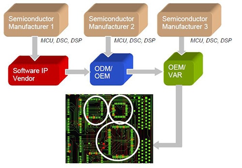
One IP protection issue they face arises from the popularity of design and support ecosystems in which multiple companies are involved in the development process of a system-level product. Each collaborating company has its own IP to protect. In the conventional approach described earlier, this IP is typically stored in firmware in the Flash memory of its own dedicated code-protected MCU (Figure 3).
The unintended result is a considerably more expensive system-level product because BOM cost and design time is increased by having multiple MCUs. In addition to increasing the system’s cost, the practice also makes it more difficult for purchasing departments to manage inventories and lead times.

Figure 3: Design ecosystems create a special IP protection challenge. (Courtesy of Microchip Technology)
Microchip Technology’s solution is its CodeGuard Security technology that allows multiple companies to securely share a single MCU’s resources. Multiple security processors may be integrated into a single 16-bit Microchip MCU or Digital Signal Controller (DSC).
CodeGuard is available on all of Microchip Technology’s 16-bit products. The degree to which basic, intermediate, or advanced security features can be enabled depends mostly on the amount of Flash memory embedded in the MCU. All PIC24F devices, such as the PIC24FJ16GA002-I/SS , for example, can implement basic security features. PIC24H devices with 64 KB on-chip Flash memory and greater, such as the PIC24HJ12GP202-I/SS, can implement advanced security features. Intermediate-level security can be implemented on DSPIC30F1010 devices such as the DSPIC30F1010-30I/SP.
CodeGuard is a versatile and robust technology that enables the following functions and processes:
- Memory segmentation and access privileges
- Segment erase/programming options for supporting secure boot loaders/kernels
- Secure interrupt handling
- Secure development and debugging
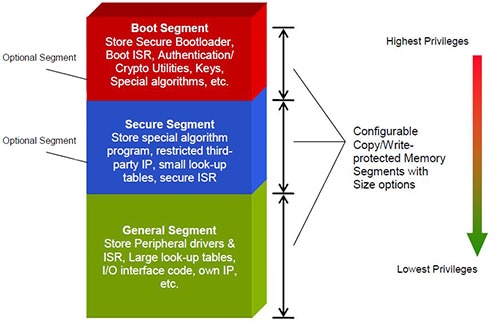
Each application has its own definition and implementation. A key feature, however, is memory segmentation and access privilege as shown in Figure 4.

Figure 4: CodeGuard memory segmentation and access privileges. (Courtesy of Microchip Technology)
Program Flash memory, RAM and EEPROM can be segmented into three protected segments of Flash memory:
- The boot segment has the highest access privileges and can be configured in many sizes. A small memory space is all that is needed for a simple yet highly secure boot loader, while a sophisticated OS would require a larger space. The boot segment can be given read or write privileges (as in a Flash update). It can call a routine or jump to any other segment regardless of whether the other segment is code-protected. It can also rewrite its own locations, a feature that gives it the ability to store and update cryptographic keys. If spurious writes are an issue for the development team, all Flash writes to the boot segment can be completely disabled. Access to the boot segment from other segments can be limited severely or left relatively open. The boot segment can also secure portions of on-chip data Flash to bar access from other segments.
- The secure segment was largely created for storing application-oriented IPs such as motor control software, acoustic algorithms, and noise-suppression algorithms. It has many size options and access from the other two sections (boot and general) can be restricted. The secure segment can secure portions of on-chip RAM and on-chip data EEPROM. When the secure segment is configured for “standard security,” the boot segment can be given unrestricted access to the secure segment. However, the secure segment and the boot segment have identical privileges when the secure segment is configured for “high security.”
- The general segment is the designated area for user-application programs such as peripheral drivers, interrupt service routines (ISRs), and large look-up tables. Its size is essentially the on-chip Flash memory minus the size of the boot and secure segments and 256 KB.
Summary
The extensive use of open-source software, the proliferation of IoT applications, and the strategic importance of protecting product IP have promoted MCU vendors to provide more powerful – and more cost-effective – security solutions. In some instances, an additional MCU dedicated to implementing security is a good choice. When multiple parties are contributing IP, however, the use of memory segmentation such as Microchip’s CodeGuard technology offers clear advantages. For 32-bit designs, ARM’s TrustZone is almost an off-the-shelf security solution.
For more information about the parts discussed in this article, use the links provided to access product pages on the DigiKey website.
免责声明:各个作者和/或论坛参与者在本网站发表的观点、看法和意见不代表 DigiKey 的观点、看法和意见,也不代表 DigiKey 官方政策。


 中国
中国