How to Deploy a Complete Bluetooth-Based IoT Design for Under $40
投稿人:DigiKey 北美编辑
2016-11-10
For developers of Internet of Things (IoT) devices, Bluetooth is a fast and safe route to connectivity and wireless system-on-chip (SoC) devices have been a ready solution for implementing Bluetooth-enabled designs. Still, time-to-market pressures are increasing, so even these highly integrated solutions fall short, requiring time and resources to add the hardware and software needed for a complete IoT design.
This article introduces a Bluetooth-enabled sensor board for that provides the Holy Grail of an instant IoT solution that can also be the foundation for custom wireless sensor IoT devices designed for home or personal use. It then describes a real-world sensing implementation example, with code, using the board’s App and on-board MEMS microphone.
Module simplify Bluetooth
Bluetooth low energy (BLE) offers multiple advantages including low power consumption, high security, and near-universal availability in mobile platforms, including smartphones, tablets, and notebooks. While wide availability of low-cost transceivers fueled rapid acceptance of Bluetooth connectivity, these transceivers still required significant expertise in RF design to build optimized designs.
Bluetooth modules simplified design, delivering a complete RF subsystem that required engineers to simply integrate an MCU and associated sub-circuits to build a Bluetooth-enabled system. Wireless SoCs such as the Silicon Labs Gecko MCU family are a recent step in this evolution, simplifying implementation while reducing design size and cost.
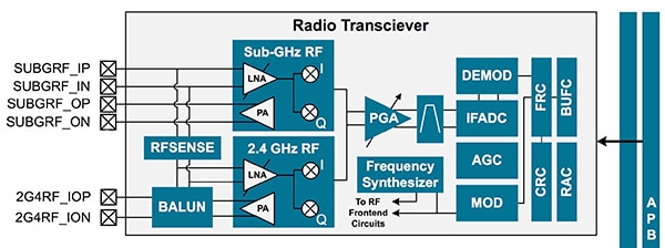
For example, the SiLabs EFR32MG1P Mighty Gecko MCU integrates a 32-bit ARM® Cortex®-M4 core, memory, crypto hardware accelerator, DC/DC converters, multiple peripherals, and a transceiver for both 2.4 GHz and sub-GHz communications (Figure 1).

Figure 1: The SiLabs EFR32MG1P wireless SoC combines a complete Cortex-M4-based system with an advanced transceiver capable of supporting sub-GHz and 2.4 GHz communications. (Image source: Silicon Labs)
Wireless sensor board
Highly integrated, power-efficient wireless SoCs offer a ready solution but nevertheless leave the designer with responsibility for implementing sensor interfaces, I/O connectivity, power management, and RF. In a battery-powered sensor node, each of these subsystems demands special attention to ensure minimal power consumption. In particular, RF design requirements can slow a project as engineers deal with RF optimization issues including antenna matching, layout, and electromagnetic interference mitigation.
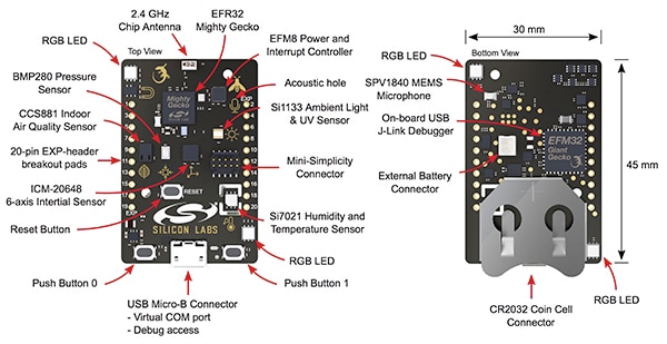
The SiLabs Thunderboard Sense board provides an immediate, extensible solution for IoT applications. Based on the EFR32MG1P wireless SoC, the board includes six sensors, 8-Mbit flash, and high-brightness RGB LEDs, as well as a bicolor LED and pushbuttons for user interactions (Figure 2). Furthermore, the Thunderboard Sense serves as a reference design for implementation of custom Bluetooth-enabled IoT designs based on the aforementioned EFR32MG1P Mighty Gecko wireless SoC.

Figure 2: The SiLabs Thunderboard Sense board provides an off-the-shelf battery-powered Bluetooth-enabled IoT design equipped with an extensive set of sensors and backed by a comprehensive software environment. (Image source: Silicon Labs)
The Thunderboard Sense is designed to operate solely from a CR2032 coin cell plugged into its onboard connector. Indeed, the design emphasizes low-power operation starting with the MCU itself. The EFR32MG1P MCU consumes only 63 μA/MHz in active mode and as little as 1.4 μA in its DeepSleep mode, which preserves RAM and keeps the real-time clock running.
In a wireless sensor design, however, power optimization requires that power management be applied to the external sensors and their conditioning circuits. The Sense board groups these peripheral circuits into power domains and uses a dedicated SiLabs EFM8SB MCU as a power and interrupt controller to manage these domains.
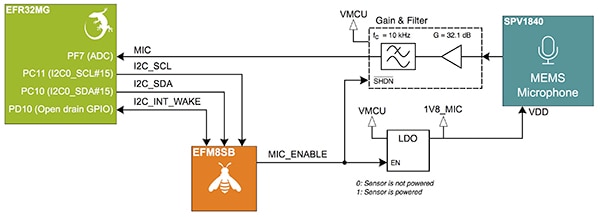
For example, to acquire data from the board's built-in MEMS microphone, the EFR32MG1P MCU writes 0x01 to the ENV_SENSOR_CTRL register in the EFM8SB peripheral controller MCU. The EFM8SB in turn enables power to the low-drop-out (LDO) regulator that powers the MEMS microphone and associated analog signal chain (Figure 3). Next, an interrupt signal from the EFM8SB causes the EFR32MG1P MCU to begin data acquisition through its integrated analog-to-digital converter (ADC).

Figure 3: The Thunderboard Sense uses a dedicated EFM8SB MCU as a power and interrupt controller to optimize power utilization in both digital and analog sensors as well as in their conditioning circuits. (Image source: Silicon Labs)
The board also offers alternative supply options for high-power applications or for line-powered operation during development. For applications that run the onboard LEDs at high intensity, for example, you can add an external battery through a connector built into the board. In addition, you can power the board through its USB connector or through its Mini Simplicity connector. The latter approach also allows performance of accurate current measurements using the external SiLabs debugger's advanced energy-monitoring feature.
Starting point
Using the Sense board and accompanying app requires only a few simple steps. After launching the Thunderboard app (from iOS App or Google Play store), you simply supply power to the Thunderboard Sense board, which immediately begins to advertise itself via Bluetooth, while blinking a green LED. When the Thunderboard Sense appears on the Thunderboard app, the user selects the device and continues working with the particular application.
Indeed, the Thunderboard Sense board and app provide a ready solution for many IoT applications. Beyond its use as an off-the-shelf solution, the Thunderboard Sense provides features that allow developers to easily extend its functionality. Along with a Micro-B USB connector and SiLabs' Mini Simplicity connector, the Thunderboard Sense also provides twenty breakout pads that developers can use to connect additional peripherals or boards. The breakout pads contain a number of EFR32MG1P MCU I/O pins, including the I2C and SPI pins, as well as main board power, 5 V rail and 3.3 V LDO power rail. Designers can also take advantage of the EFR32MG1P MCU's flexible pin routing to access any of its integrated peripherals.
Besides its utility as an off-the-shelf solution, the Thunderboard Sense hardware and accompanying software provide a starting point for custom IoT applications. The design addresses common interface issues associated with I2C and SPI digital sensors as well as analog peripherals and an RF antenna. To help speed development of custom designs based on the Sense board, SiLabs provides complete schematics for each peripheral and IO, including a suitable 2.4 GHz matching network connecting the MCU's 2.4 GHz RF I/O pins to the on-board chip antenna.
For example, the schematic for the MEMS microphone circuit provides a full design of an analog signal chain for MEMS microphone output. In that circuit, Texas Instruments TLV342S op amps are used in a 32.1 dB gain amplifier stage and in a first-order active low-pass filter for the output of the Knowles SPV1840 MEMS microphone (Figure 4). The design connects the signal chain's MIC output to the MCU's 12-bit successive approximation register (SAR) ADC for microphone data acquisition.
Figure 4: Along with hardware and software for the Thunderboard Sense kit, Silicon Labs provides assembly drawings, bill of materials, and full schematics, such as this analog signal conditioning circuit used for MEMS microphone signal acquisition. (Image source: Silicon Labs)
Software design and debug
Silicon Labs supports the Thunderboard Sense kit with an extensive set of software libraries available for use with its free Simplicity Studio development environment. Along with software libraries for MCU hardware functions, the package includes a board-support package (BSP) for the Thunderboard Sense, as well as accompanying sample C code. For example, the SenseApp module provides a BLE application that transmits data from its full set of sensors to a smartphone app.
Besides serving as a functioning application, the SenseApp code illustrates key software design patterns for implementing an IoT sensor design based on the EFR32MG1P MCU. For example, the BLE stack takes over the real-time clock, preventing its use for timing events in the application itself. The SenseApp sample code demonstrates the use of the MCU software timer to periodically poll various software functions including those for sensor data capture.
In the SenseApp application, the main routine initiates the device and begins an endless loop that waits for an event and calls an application event handler to process that event (Listing 1).
Copy
while (1) {
struct gecko_cmd_packet* evt;
/* Check for stack event. */
evt = gecko_wait_event();
/* Run application and event handler. */
appHandleEvents(evt);
}
Listing 1: A utility loop in the SenseApp main routine continually loops, handing off events to an event handler to invoke operations such as sensor sampling. (Listing source: Silicon Labs)
Located in app.c, appHandleEvents calls RADIO_bleStackLoopIteration() (located in radio_ble.c) if the device is not in Bluetooth advertising mode. If the connection is active, this routine in turns calls connectionActiveIteration() (in radio_ble.c), which provides the core data-sampling function.
The connectionActiveIteration() routine checks the status of the onboard buttons and periodically calls service routines responsible for updating data from each of the board's sensors. Finally, this routine checks for microphone activity and if the microphone is active, it initiates microphone data acquisition by setting the sound level and starting microphone data collection with a call to the MIC_start() function (Listing 2).
Copy
******************************************************************************/
void MIC_start( uint32_t nSamples )
{
if( nSamples > sampleBufferLen ) {
sampleCount = sampleBufferLen;
}
else {
sampleCount = nSamples;
}
if( !dmaBusy ) {
/* Configure DMA */
DMADRV_PeripheralMemory( dmadrvChannelId, // channelId
dmadrvPeripheralSignal_ADC0_SCAN, // peripheralSignal
(void *) sampleBuffer, // *dst
(void *) &( ADC0 ->SCANDATA ), // *src
true, // dstInc
sampleCount, // len
dmadrvDataSize2, // size
dmaCompleteCallback, // callback
NULL ); // *cbUserParam
adcEnable( true );
dmaBusy = true;
sampleBufferReady = false;
}
return;
}
Listing 2: Located in the BSP package, the mic.c module includes microphone support routines, including the MIC_start() routine, which performs microphone data acquisition by initiating a DMA transfer from the MCU's on-chip ADC. (Listing source: Silicon Labs)
The MIC_start() routine initiates a DMA transfer from the MCU's on-chip ADC (dmadrvPeripheralSignal_ADC0_SCAN) using a the DMADRV_PeripheralMemory routine in the dmadrv.c module. (As noted earlier, the output of the MEMS microphone signal chain is tied to the MCU ADC.) This module is part of the SiLabs emdrv EnergyAware drivers library available on github.
On completion of the ADC data acquisition sequence, the dmaCompleteCallback() callback routine disables further ADC sampling and prepares the device for the next round of sampling. Moving beyond this basic application, developers can build on these code samples and fundamental design patterns to implement more sophisticated application-specific functionality.
Conclusion
Bluetooth low energy offers a particularly compelling connectivity option for IoT applications designed to work with mobile apps. Although wireless SoCs have eased the burden of design, even these highly integrated devices require additional effort for implementing the additional hardware and software components required in a fully functional IoT design. Based on the Silicon Labs Mighty Gecko wireless SoC, the SiLabs Thunderboard Sense kit provides a complete off-the-shelf solution for mobile-connected IoT devices and serves as the starting point for more sophisticated custom IoT designs.

免责声明:各个作者和/或论坛参与者在本网站发表的观点、看法和意见不代表 DigiKey 的观点、看法和意见,也不代表 DigiKey 官方政策。


