An Introduction to Power-over-Ethernet
投稿人:电子产品
2013-09-10
By combining power and communications over a single CAT 3 or CAT 5 cable, engineers can construct low-maintenance Ethernet networks quickly and inexpensively compared with installations employing separate systems. It is not a surprise that the technology has been rapidly embraced and formalized under an Institute of Electrical and Electronics Engineers (IEEE) standard. Dubbed “Power-over-Ethernet” (PoE), key advantages of the technology are its simplicity and the fact that power is available wherever there is a data socket.
This article provides an introduction to PoE and the higher-power PoE+, outlining the standards, explaining the component parts, Powered Devices, Power Sourcing Equipment, “midspan”, and “endspan” Ethernet switches and splitters, and describing a simple system.
The early days of PoE
PoE first emerged as an answer to the problem of powering Voice over Internet Protocol (VoIP) phones. Traditional phones took their power directly from the copper wires carrying voice calls. However, increasingly popular VoIP phones were not connected to these conventional circuits, instead taking calls over the Ethernet cables of a company’s Local Area Network (LAN). The Ethernet cables did not carry power, so the VoIP phones had to be plugged into the mains supply via an adapter. It was a less-than-elegant solution, and if the building power was lost, the phones died.
In 2000, telecommunications equipment vendor Cisco was the first company to mimic the traditional phone system by introducing proprietary technology that allowed Ethernet cables to carry a 48 VDC supply to power VoIP phones (Fig.1). However, PoE really gained momentum in 2001 and 2002, as other manufacturers, particularly Wireless Access Point makers, took advantage of the technique.

The technology eventually caught the attention of IEEE, which had been responsible for setting the “Standard for Ethernet” (IEEE 802.3) as far back as 1983. The organization believed it was crucial to create a standard version of PoE so that any manufacturer could make their products “PoE-ready”. The work was assigned to a working subcommittee of the IEEE 802.3 Ethernet Committee and named “802.3af”. By June, 2003 the working subcommittee ratified the IEEE 802.3af PoE Standard. In 2009, a second standard, IEEE 802.3at, was ratified which defined a similar technology that could handle more power.¹
What is defined in the standard?
IEEE 802.3af details a PoE technology designed to provide up to 15.4 W of DC power (minimum 44 VDC and 350 mA) to each device.² (Due to losses in the cable, only 12.95 W is guaranteed to be available at the equipment to be powered.)
The technology uses a single, standard RJ45 connector and CAT 5 (or even CAT 3) cable, and can handle tens of watts. Once the Ethernet network is installed for communication, it can also be used for power, saving on materials, labor, installation time, and ongoing maintenance costs.
Power may be transmitted on the unused conductors of the Ethernet cable, since only two of the four pairs in CAT 5 cabling is required for the typical 10 to 100 Mbps physical layers (this technique is referred to as “Alternative B” in the IEEE standards). Power also may be transmitted on the data conductors of the cable by applying a common-mode voltage to each pair. Because Ethernet uses differential signaling, this does not interfere with the cable’s data transmission (“Alternative A” in the standards).
IEEE 802.3af defines two types of PoE devices, Power Sourcing Equipment (PSE) and the Powered Device (PD). A PSE draws power from its own conventional power supply and then manages the power sent over the Ethernet cable network to the PD, which takes the power it needs via an RJ45 connector without needing a built-in power supply. PoE is able to power PDs over typical Ethernet cable runs of up to tens of meters. PDs are devices such as the original VoIP phones and Wireless Access Points, security cameras, Point-of-sale (POS) terminals, temperature control systems, and even in-flight entertainment systems.
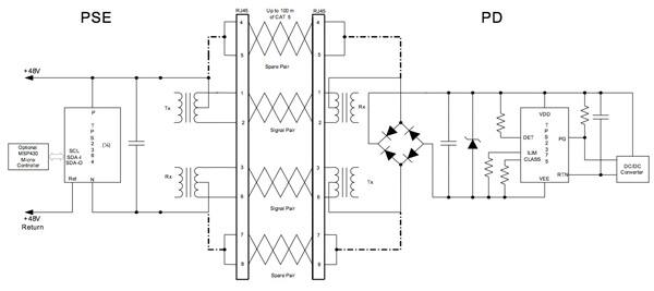
In addition to standardizing existing practice for spare-pair and common-mode data pair power transmission, the IEEE PoE standards provide for signaling between the PSE and PD. This signaling allows conforming devices to be detected by the PSE, avoiding damage to non-PoE devices attached to a network. The PSE and PD ‘negotiate’ the amount of power required or available. To detect a PD, the PSE applies a DC voltage between 2.8 and 10 V across the conductor. The PSE then determines if there is a PD connected by measuring the loop current. The PD should present a resistive load between 19 to 27 kΩ with a parallel capacitor of 120 nF or less as a signature. Figure 2 shows a schematic of a PSE powering a PD.

Enhancement of the standard
While PoE can supply around 13 W to the PD, some devices could benefit from more power (for example, cameras with pan, tilt, and zoom (PTZ) capabilities). To cater for these products, a second standard, IEEE 802.3at, was introduced in 2009. Also known as “PoE+”, the technology can supply up to 25.5 W DC to the PD. The PSE provides 50 to 57 VDC compared to 44 to 57 VDC for PoE. Current for PoE+ is increased to 600 mA compared to the earlier technology’s 350 mA.
PoE+ uses CAT 5 cable (which has eight internal wires, compared with CAT 3’s four wires) only, which decreases the chance of possible impedance and reduces power dissipation. Moreover, PoE+ allows network administrators greater capabilities such as providing new remote power diagnostics, status reporting, and PD power management (including remote power cycling of embedded devices).
Finally, PoE+ provides dynamic power allocation, optimized power distribution, and good power-supply utilization leading to increased system efficiency and reduced costs.³ Table 1 compares PoE and PoE+.
| Property | IEEE 802.3af | IEEE 802.3at Type 2 |
| Power available at PD | 12.95 W | 25.50 W |
| Maximum power delivered by PSE | 15.40 W | 34.20 W |
| Voltage range (at PSE) | 44.0-57.0 V | 50.0-57.0 V |
| Voltage range (at PD) | 37.0-57.0 V | 42.5-57.0 V |
| Maximum current | 350 mA | 600 mA |
| Power management | Three power class levels | Four power class levels |
| Supported cabling | Category 3 and Category 5 | Category 5 and above |
| Supported modes | Alternative A and B | Alternative A and B |
Endspans and midspans
PSEs can be implemented as endspans (an Ethernet PoE-enabled switch) or as midspans (a power hub used in conjunction with a non-powered Ethernet switch already in place on the network). PDs can receive power equally well from endspans or midspans.
Endspans apply power directly to the devices. Under the specifications, endspans can use either the spare pairs or the data pairs in the cable, which can also be used for Gigabit Ethernet transmissions. Endspans require PoE-enabled switches, and therefore, tend to be specified for new installations that demand fresh equipment.
Midspans use an intermediary-powered patch panel, or ‘injector’, placed between an existing Ethernet switch and the PDs. The midspan is typically located adjacent to the switch, and is then considered to be the PSE, allowing the cable to be run unencumbered to remote devices. The specification allows midspans to use only the spare pair in the cable; consequently they cannot be used to send power over data lines such as Gigabit Ethernet connections.
There is a range of midspan injectors readily available for addition to a legacy Ethernet network. Laird Technologies supplies its POE-48I power supply for this application. The power supply is auto-ranging on the input side and has a regulated voltage output. The device will function with any equipment that is compliant with the IEEE 802.3af standard. The POE-48I has a single port and can deliver 48 V at 500 mA for up to 24 W.
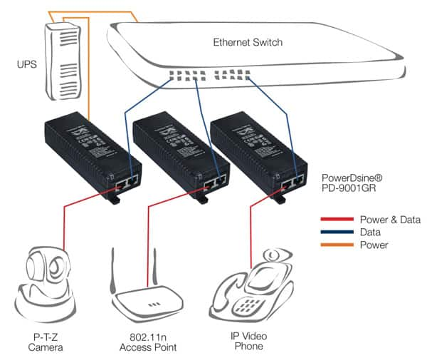
Microsemi Analog Mixed Signal Group offers a single-port, midspan injector that complies with the higher-power IEEE 802.3at standard, the PowerDsine 9001GR. Generating up to 30 W at 55 V, the 9001GR enables remote power for a new range of applications including PTZ cameras and videophones. The device is backward compatible to IEEE802.3af, and can power existing 10/100Base-T network devices and emerging wireless 1000Base-T devices such as WiMAX and IEEE 802.11n Wireless Access Points. Figure 3 illustrates typical applications.

Many multiport midspans are also available. Phihong supplies midspans with 8, 16, and 24 ports. The POE370U is a 24-port midspan injector compliant with IEEE802.3af. Each port supplies 15.4 W without additional power management. The unit offers detection, disconnect, and overload protection, and can be supplied with a 1 U rack-mounting kit.
The midspan suppliers can also offer ‘splitters’. These are devices that use a PoE input that is split into two outputs: data and power. The power can be redirected into the end device using more conventional means, such as a DC cable. Splitters act as an intermediary device between a compliant PSE and a non-compliant PD.
Laird Technology supplies the POE-12S-AFI active PoE splitter which can accept PoE power from any IEEE 802.3af router or power supply. The unit incorporates overload and short-circuit protection and will shut-down power immediately when a short circuit is detected without any damage to the PoE system.
Choosing between an endspan or midspan PoE network
Endspans cost more to implement and operate only with PDs defined by the IEEE standard, but there are some good reasons for selecting this technique. For example, engineers tend to select endspan switches if they are replacing all the old switches, or if the installation is new.
Another reason to use endspans is to avoid the untidy and inconvenient extra patch cords, and extra work, involved with connecting a conventional Ethernet switch to a midspan PoE hub. Also, two devices instead of one doubles the potential points-of-failure and makes life more complex for administrators that work in companies that insist on a separate IP address for every piece of equipment on the network.
Engineers selecting endspan switches should be aware that many endspan units can only provide a maximum of 200 W, so a 24-port switch can only supply a maximum of 8.3 W per port, short of the 15.4 W maximum power specified in the PoE standard.
Engineers that have relatively new Ethernet switches already in place favor midspan switches because it would be expensive to replace the switches just to gain PoE functionality. However, the engineer must ensure that the switch manufacturer is happy for the network to support midspan products and that there is sufficient space to accommodate them.
From an electrical perspective, midspan switches are preferred if the network engineer wants to use non-standard voltages like 24, 12, and 5 V for particular PDs, and is keen to maximize the amount of power available from each port. Midspan switches are also a useful option for networks that comprise many legacy devices that have their own power sources as well as PoE devices.
Midspan switches tend to have longer warranties compared to endspans (two years compared to one), and can work with both standard and proprietary applications.
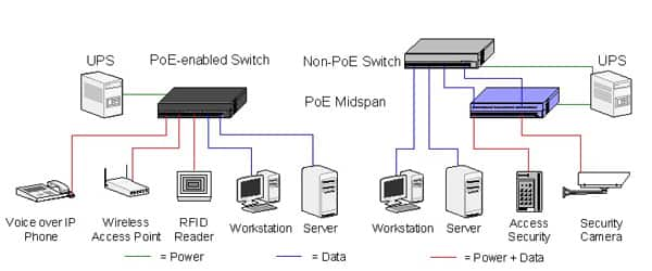
Figure 4 shows networks constructed using endspan and midspan switches.

Traditionally, PSEs incorporated discrete circuitry divided into the communication interface between the power supply, Ethernet network, and the power supply itself. However, to make implementation even easier, the silicon vendors have brought out a range of integrated PSE controllers to optimize the operation of a PoE+ installation.
These controllers reduce the complexity and number of external components that are required for PoE and PoE+ equipment by combining the interface circuitry with the linear regulator or switching power supply that converts the supply voltage to the 50 to 57 VDC suitable for the Ethernet cable. (For more information about these components, see the TechZone article “Power-over-Ethernet Adapts to Meet Higher Demand”).
Is PoE++ next?
Since its development in the early part of the century, PoE (and more recently PoE+), has become a popular technology particularly for commercial and industrial applications. The predominant market force today is the requirement to connect IP security cameras and Wireless Access Points, but other manufacturers are introducing a steady stream of PDs that take advantage of PoE and PoE+, such as sensors, detectors, security access devices, displays, and human machine interfaces (HMI).
The technology is relatively simple to implement, especially for new installations, and the introduction of midspan switches has eased the challenge of adding PoE to legacy networks. The introduction of PoE+ has increased the power available for PDs leading to the introduction of new applications that were too power greedy to operate using the older technology.
Nonetheless, PoE technology continues to evolve because engineers are keen to add new PDs that require even greater power; there are already proprietary PoE systems available which supply as much as 60 W. These technologies do not adhere to the current standards and are not interoperable, which can be harmful to non-compatible hardware, but they are setting a precedent for yet a higher-power version of the standard to be developed.
For more information about the parts described in this article, use the links provided to access product pages on the DigiKey website.
References:
- “Certified Wireless Network Administrator Official Study Guide,” David D. Coleman; David A. Westcott, Sybex, April 2009.
- IEEE 802.3-2005.
- “PoE vs. PoE+,” Jeffrey Bausch, Electronic Products, August 2011
免责声明:各个作者和/或论坛参与者在本网站发表的观点、看法和意见不代表 DigiKey 的观点、看法和意见,也不代表 DigiKey 官方政策。


