制造商零件编号 DEV-13736
TEENSY 3.2 K20 EVAL BRD
SparkFun Electronics
Introduction
Basically, we’re going to take in live video from a webcam, do a little magic in Processing to translate the color values for the RGB panel, then push them out to a Teensy 3.1 Microcontroller (using the Arduino IDE), which we will program to take in the color values from Processing and turn on the proper LEDs to create a pixelated image of whatever the webcam is pointed at. Fun!
Suggested Reading In addition to the hardware, you may want to take a look at some background material that's relevant to this projcet. Here are some good links to get you started:
Setup
Once you've got the hardware, your first stop is our RGB Panel Hookup Guide - specifically the part about powering the panel. We'll be powering our project the exact same way, so go ahead and take a little detor over there. Note: Just do the power supply part, NOT the hardware hookup - our configuration is different.
Your power supply should look like this when finished:
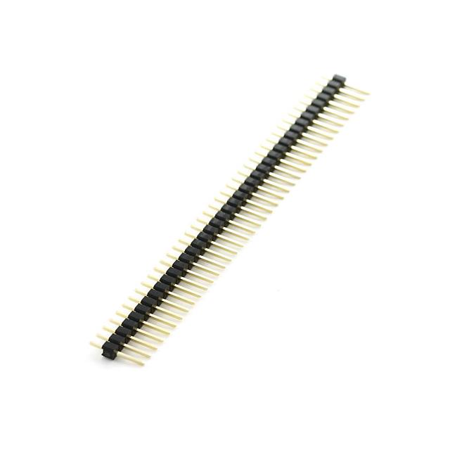
You’ll also want to solder some headers (the ones in the wish list) onto your Teensy so we can stick it into a breadboard and hook it up to the RGB Panel.
It should look something like this
We’ll be programming using Processing and Arduino - so you’ll want to download both of those if you don’t have them already (the latest versions should work just fine). In order to program the Teensy from the Arduino IDE, you’ll also need to install the Teensyduino library (instructions from the link).
Hardware Hookup
Here are the pin connections between LED panel connector and the Teensey 3.1:
Panel connector pin numbering convention: Pin 1 is top left (R0), pin 2 is to the right of pin 1, pin 3 is below pin 1, pin 4 is to the right of pin 3, etc. Pin 16 is the bottom right.
And for handy reference, here’s a pinout chart for the Teensy 3.1:
When connecting into the ribbon cable connector, pay attention to the notch that signifies polarity. When looking at the cable with the notch facing up and on the left side, R0 (pin 1) should be at the top left.
Both red and blue wires should be on the notch side, the greens should be on the other.
Your hardware hookup should look something like this when you’re done.
Teensy Code
The Teensy code is fairly long and involved, so we’re just going to embed the whole thing here.
As Codebender doesn’t currently support the Teensy boards, you’ll have to copy and paste the code into an Arduino sketch on your computer.
Remember to have the board type (Teensy 3.1), USB Type (serial), and CPU Speed (96kHz overclock) set correctly under the ‘Tools’ menu in the Arduino IDE.
Processing Code
Below is the Processing code in its entirety - BUT - there are a few lines you will most likely need to change, so hold your horsies for a minute.
This line, where we choose our serial port:
will need to reflect the actual serial port your Teensy 3.1 is connected to. So you’ll want to replace the ‘5’ in brackets with the number reflective of the array index belonging to your port, which is to say: running this code will cause Processing to print out a list of serial ports, and you need to pick the place in this list that your Teensy is connected to, starting from zero (because it’s an array).
Here’s a screenshot from my computer - the Teensy is on /dev/tty/usbmodem40671 - so I count from zero from the upper left and get 5, which is why there’s a 5 in my code. Make sense? Yeah, me neither.
We need to go through a similar process with picking the port our USB webcam is connected to.
In this case, you would want to replace the ‘3’ above with the place you find something like ‘USB 2.0 Camera, size=320x240, fps=30’ - in my case it was the fourth one down, and since we count from zero, I put in a ‘3’.
We’re using the 320x240 resolution because it makes the math a little easier since we have 32 rows of LEDs. Feel free to experiment with the other settings to see what happens.
Putting it All Together
Now for the big finish! Plug in the RGB Panel power supply to a wall outlet, the Teensy 3.1 and webcam get plugged in to your computer’s USB ports. Now start the Processing sketch; it will take a little bit to start up as it goes through all the available cameras (if you have a Mac you’ll notice the green light on your iSight flash on and off once or twice). Once it starts up, a little preview box will pop up on your computer, and your RGB matrix should come to life, with the image from the webcam showing up (somewhat pixelated) on the RGB panel.
For photos, we set it up to look at a SparkFun flame sticker:
The webcam is attached to the tripod arm, facing downward at the flame. Pretty sweet!
You may have noticed a few scraps of red cardboard on top of the sticker. Turns out the lighting in the studio and the reflectivity of the sticker (it’s shiny) caused the sticker to get washed out - so we improvised.
Resources & Going Further
A lot of people have been playing around with these awesome RGB LED panels and have developed some pretty sweet tools and hacks to explore and integrate into your own experiments. Here are a few I dug up, and please suggest other resources in the comments!
That’s all I’ve got for now - post your projects in the comments below - we’d love to check them out!