8-Bit Capacitive Synth
2018-07-16 | By Bantam Tools
License: GNU Lesser General Public License Milling Machines
Courtesy of Bantam Tools
Can’t get enough 80's synth music? This project is for you! Our 8-Bit Capacitive Synth will have you rocking out to infectiously simple computerized tones with just the touch of a button.
In this intermediate build, we’ll start by using a .brd file to mill our PCB on the Bantam Tools Desktop PCB Milling Machine, then we’ll get practice soldering surface-mount components and program our PCB with Arduino. If you’re new to Arduino, be sure to check out their handy Getting Started guide. This tutorial assumes that you have previous experience with the Bantam Tools Desktop PCB Milling Machine. If you're just getting started, check out our series of introductory guides.
Let’s get going! Beep boop bloop!
Tools, Materials, and Files
TOOLS
Computer with Bantam Tools Desktop Milling Machine Software installed
Soldering iron and solder
MATERIALS
Printed circuit board blanks, FR-1, 4"x5"
Ceramic resonator, 16MHz
Microcontroller, ATmega328, with Arduino bootloader
IC chip socket, 28-pin, through-hole
Headphone jack, 1/8" (3.5 mm), through-hole, PCB-mount style with 3 leads
Computer speakers or other speakers with a 3.5mm jack, e.g., car stereo or a portable speaker
Painter's tape (optional)
FILES
Step 1: Gather your supplies
Get your tools and materials ready to go. Make sure you have the latest version of the Bantam Tools Desktop PCB Milling Machine Software installed on your computer. Fire up your computer and your Bantam Tools Desktop PCB Milling Machine.
Step 2: Mill the board
Download CapacitiveSynth.zip and load CapacitiveSynth.brd into the Bantam Tools Desktop Milling Machine Software.
Attach double-sided tape to the bottom of the FR-1 board and measure the thickness of the board plus tape using calipers.
Attach the FR-1 blank to the bed, making sure the bottom and left edges line up (home position is the front left corner).
Set up your material in the software by selecting single-sided FR-1, standard 5"x4" size. Check the sizes and add the measured thickness.
In the imported plan file window of the .brd you just opened, add the 1/32” Flat End Mill to the first drop-down and the 1/16” Flat End Mill to the second.
Makes sure that Traces, Holes, and Outlines is enabled in the imported plan window.
When everything looks good, select "Mill All Visible."
The software will ask you to confirm the action and will prompt you through the tool-location sequence before it does any actual cuts.
The machine will pause and prompt you through the tool change when necessary.
When the board is finished, carefully remove it using isopropyl alcohol and a scraper.
Step 3: Solder the components to the board
With our PCB milled, next we'll move on to soldering the board. All of the solder joints on this project are surface-mount or need to be completed on the copper side of the board.
First, we'll solder the IC socket:
Orient the socket so the U-shaped divot is facing the longer side of the board.
Insert the pins through the holes until they touch the flat surface, and lightly nudge the socket away from the board. You’ll be soldering the pins at the entry point on the copper. Make sure the pins are still going through the holes.
Once the soldering is complete, take the ATmega328 chip and gently bend the pins against the table until they're straight. This will allow them to fit into the socket.
Insert the ATmega328 chip into the socket to check the fit. If the pins are still too wide, bend them again.
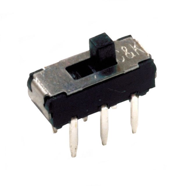
Solder the power switch:
Place the switch on the 6 copper pads in front of the IC socket's U-shaped divot, as shown in the picture below.
Getting the switch lined up can be tricky. We recommend using painter's tape, anti-static tweezers, or picks to hold it in place. You can also tin one pad on the board and reheat it once the switch is in place. This may require several attempts. Be patient.
Solder the resonator:
Use pliers to bend the first millimeter or two at 90°.
Make sure the resonator is situated so the identifying numbers are facing (or closest to) the board. The direction of the resonator is very important for the overall function of the synth.
Put the bent part of the pins through the holes.
Solder the pins.
Solder the headers:
Pull out the second from the last pin with pliers.
Insert the pins into the holes, leaving enough metal exposed so that you can get to it with the soldering iron.
Solder the pins to the board.
Solder the resistor and capacitor:
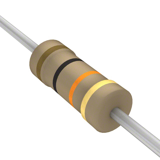
Bend the leads of the resistor and feed them through the holes.
Solder the resistor and snip off the leads on the back.
Insert the capacitor into the holes and solder it, snipping off any leads on the back.
Note: It doesn’t matter which direction these components sit in the board, as neither have polarity.
Solder the battery holders:
Apply a small pad of solder to the middle of each battery pad area on the board before soldering the holders into place. This will help the battery make contact with the board.
Orient the holders so that the batteries can be loaded from the edge of the board.
Carefully solder the holders' ends to the pads, making sure they don't get bumped out of alignment before the solder cools. You can secure them in place with painter's tape.
Make a big puddle of solder that fills the whole pad and covers the little tabs.
Solder the 3.5mm jack:
Insert the pins into the holes, but leave enough metal exposed so that you can still get a soldering iron to the front pin.
Solder the pins.
Solder the itty-bitty surface-mount LED:
Yes, it's really, really small and fiddly, but we promise it's really cool!
Orient the positive end downward. It looks like a horizontal line. The negative side is more vertical. If you can't tell which is which, you can test it by setting a multimeter to the continuity test setting and touching the probes to the ends until it faintly lights up.
Due to the very small and delicate size of the LED, we recommend the use of solder paste, flux, or pre-tinning one pad.
We also recommend using anti-static tweezers to hold it in place while soldering.
Solder it to the board. You're done!
Your board should now look like this, with all the components soldered in place:
Step 4: Program the chip
In order to use the ATmega328 chip as a synthesizer, you need to program it. There are several ways to do this, but we'll choose between two: FTDI cable or Arduino.
If you have an FTDI cable, you can simply put the long male header pins into the headers on the board and then plug the cable in directly to those pins. Make sure that the black ground wire goes to the pin on the end whose neighboring pin we removed earlier. You can also run jumper wires between the cable and the headers on the board.
Here's the pinout configuration:
Reset > Synth header pin 1
Digital pin 0 > Synth header pin 2
Digital pin 1 > Synth header pin 3
5V > Synth header pin 4
GND > Synth header pin 6
If you have an Arduino and no FTDI cable, you can remove the ATmega328 chip from the Arduino Uno board and use the ATmega chip from your synth. We’ll be programming our chip directly on the Arduino board. It’s truly that easy: Simply replace the Arduino’s ATmega chip with yours.
Here's how to remove the chip from your Arduino:
Unplug the USB cable and any other power sources.
Gently slide a small flat-head screwdriver or other flat, stiff tool under one end of the chip. You may have to wiggle it to get it under there.
Once you pry up one end a little bit, stop and do the same for the other end.
Keep doing this until you can pull the chip out of the socket.
Note: If you accidentally bend one of the pins, don't worry. Just bend it back to its original shape, and it'll be fine.
Now program the chip:
Open the Arduino IDE and load the sketch.
In the Tools menu under Board, select Arduino Uno.
In the Tools menu under Serial Port, select your Arduino or FTDI cable. It will begin with /dev/tty.usbserial.
Click the Upload button to program the chip.
Make sure to add the pitches folder in a tab inside the sketch.
Step 5: Play sweet music!
You're done! Now let’s try it out:
Insert batteries into both battery holders.
Flip the switch to see the LED light up, signaling there’s power.
Plug your speakers into the 3.5mm jack and turn them on with low volume.
While touching one of the keys on the left, touch one of the keys on the right. You should hear a tone.
Congratulations! You’ve now made your very own synth. If you build one, we'd love to see it! Tag your build pics on social channels with #bantamtools or @bantamtools. Alternately, you can always send us your pics via support@bantamtools.com.
Troubleshooting Tips
If your capacitive synth isn't working quite right, try these troubleshooting tips.
Use a multimeter and double-check all of your solder point, especially with the IC socket.
Make sure the CR2032 batteries are pushed all the way in the battery holder. A short can occur in the circuit if the battery isn’t in the holder properly.
File Downloads:
CapacitiveSynth.brd (40KB)
pitches.h (2KB)
CapacitiveSynth.ino (9KB)


